Verify communication – Wavetronix Click 400 (900 MHz radio) (CLK-400) - User Guide User Manual
Page 151
150
CHAPTER 13 • CLICK 200
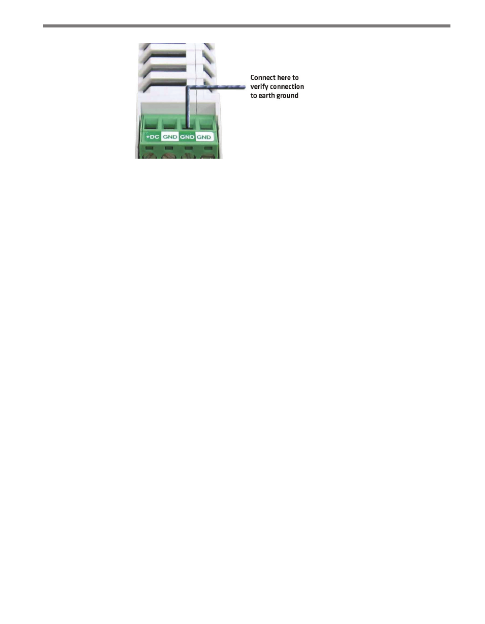
Figure 13.5 – Verifying Earth Ground
3 The resistance should measure less than one ohm. If not, the most likely problem is the
DIN rail is not making connection to earth ground through the chassis of the cabinet.
The Click 200 cards have a connector on the bottom that snaps on the DIN rail that provides
the connection to earth ground. If the DIN rail is not making a good connection to earth
ground, connect a 16 AWG (or larger) wire to the DIN rail with a bolt and run that wire
directly to an earth ground terminal.
Verify Communication
Follow the steps below to verify the communication connections:
1 Check the RS-232 connection by plugging a straight-through RS-232 cable between a
laptop and the DB-9 connector on the Click 200.
2 Launch SmartSensor Manager and connect via a serial connection. If there are prob-
lems connecting, verify that the cabling is set up correctly.
3 Check the RS-485 connection to the SmartSensor using a Click 304 RS-232 to RS-485
converter. Attach the Click 304 to the T-bus (see Chapter 2 for more on T-buses) and
then plug a straight-through RS-232 cable between a laptop and the DB-9 connector
on the faceplate of the Click 304.
4 Launch SmartSensor Manager and connect via a serial connection. If there are prob-
lems connecting, verify that the cabling is set up correctly.
Once communication and ground connections have been verified, the installation of the
Click 200 is complete.
- Click 421 (bluetooth to serial converter) (CLK-421) - User Guide Click 342 (lean managed ethernet switch) (CLK-342) - User Guide Click 341 (lean managed ethernet switch) (CLK-341) - User Guide Click 340 (lean managed ethernet switch) (CLK-340) - User Guide Click 331 (unmanaged ethernet switch) (CLK-331) - User Guide Click 330 (unmanaged ethernet switch) (CLK-330) - User Guide Click 304 (RS-232 to RS-485 converter) (CLK-304) - User Guide Click 305 (RS-232 to RS-485 converter) (CLK-305) - User Guide Click 301 (serial to ethernet converter) (CLK-301) - User Guide Click 100 (16 output contact closure) (CLK-100) - User Guide Click 104 (4-channel DIN rail contact closure) (CLK-104) - User Guide Click 110 (4-channel contact closure eurocard) (CLK-110) - User Guide Click 112 (detector rack card) (CLK-112) - User Guide Click 114 (detector rack card) (CLK-114) - User Guide Click 120 (screw terminal relay) (CLK-120) - User Guide Click 121 (spring cage relay) (CLK-121) - User Guide Click 200 (surge suppression) (CLK-200) - User Guide Click 201 (1 amp AC to DC converter) (CLK-201) - User Guide Click 202 (2 amp AC to DC converter) (CLK-202) - User Guide Click 203 (UPS and battery) (CLK-203) - User Guide Click 204 (4 amp AC to DC converter) (CLK-204) - User Guide Click 210 (AC circuit breaker) (CLK-210) - User Guide Click 211 (AC outlet) (CLK-211) - User Guide Click 221 (DC surge protector) (CLK-221) - User Guide Click 222 (system surge protector) (CLK-222) - User Guide Click 223 (dual-485 surge protector) (CLK-223) - User Guide Click 230 (AC surge protector) (CLK-230) - User Guide Click 250 (wireless surge protector) (CLK-250) - User Guide