Physical features, Installation – Wavetronix Click 400 (900 MHz radio) (CLK-400) - User Guide User Manual
Page 169
168
CHAPTER 18 • CLICK 221
Physical Features
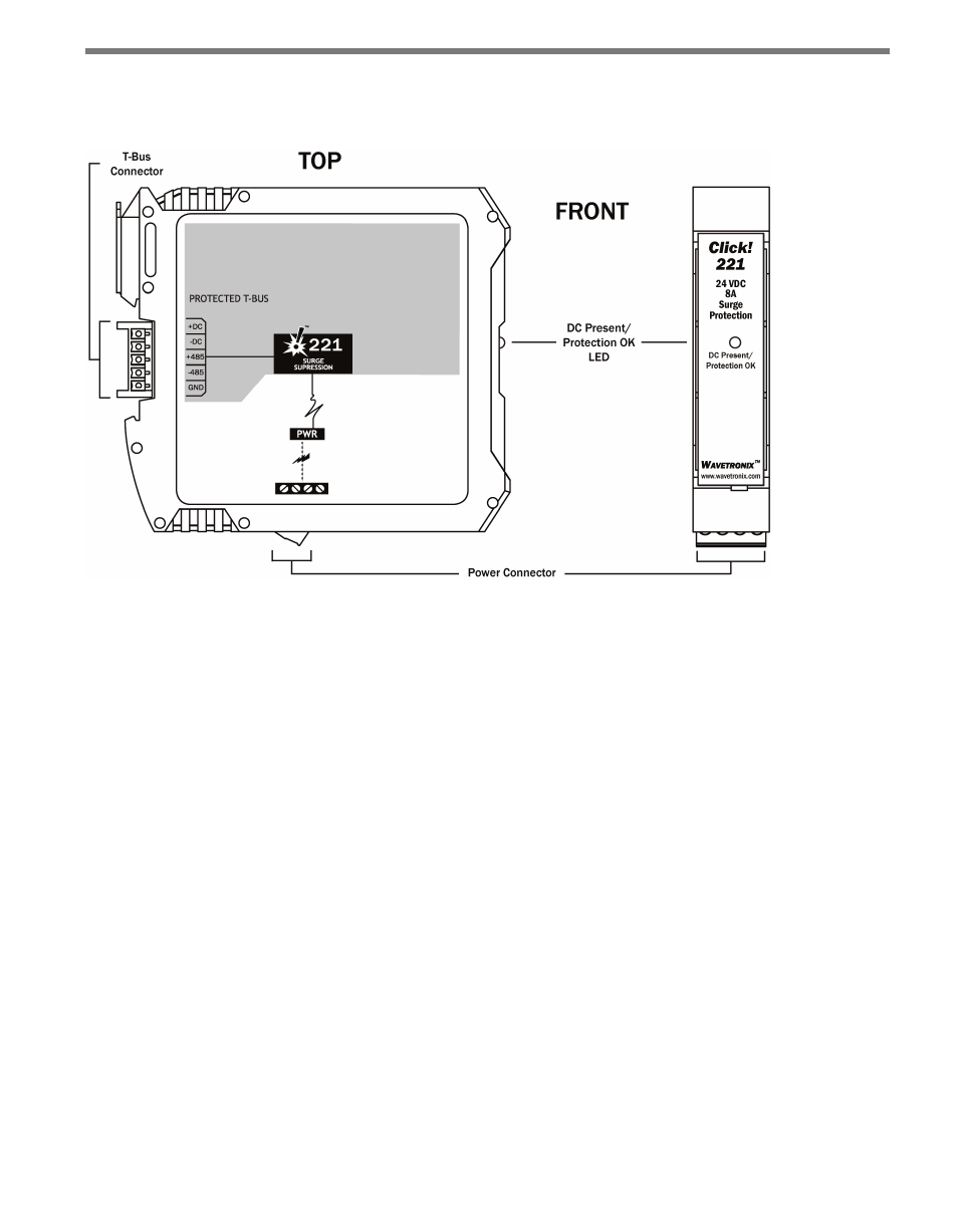
Figure 18.2 – Diagram of the Click 221
The bottom of the Click 221 has a screw terminal block with four screw terminals—+DC,
-DC and two PE terminals—for DC power.
The back of the Click 221 features a 5-position connector that plugs into a T-bus connector
and provides power to the device. It also passes that power to all other devices on the T-bus.
A pinout diagram is provided on each individual unit as a reference in the field.
The faceplate has an LED used for monitoring the device: if the LED is on, the device has
power and the surge protection is functional.
Installation
To install and wire the Click 221:
1 Mount the Click 221 on the T-bus it is going to protect.
2 Wire power from the DC power source into the +DC and -DC terminals on the bottom
of the device.
3 Wire from one of the PE terminals to a good earth ground. If the device is in a cabinet,
there will likely be a central grounding point—such as a grounding lug—for just such
a purpose.
4 Watch the LED. If it comes on, the device has power and the surge protection is ready.
- Click 421 (bluetooth to serial converter) (CLK-421) - User Guide Click 342 (lean managed ethernet switch) (CLK-342) - User Guide Click 341 (lean managed ethernet switch) (CLK-341) - User Guide Click 340 (lean managed ethernet switch) (CLK-340) - User Guide Click 331 (unmanaged ethernet switch) (CLK-331) - User Guide Click 330 (unmanaged ethernet switch) (CLK-330) - User Guide Click 304 (RS-232 to RS-485 converter) (CLK-304) - User Guide Click 305 (RS-232 to RS-485 converter) (CLK-305) - User Guide Click 301 (serial to ethernet converter) (CLK-301) - User Guide Click 100 (16 output contact closure) (CLK-100) - User Guide Click 104 (4-channel DIN rail contact closure) (CLK-104) - User Guide Click 110 (4-channel contact closure eurocard) (CLK-110) - User Guide Click 112 (detector rack card) (CLK-112) - User Guide Click 114 (detector rack card) (CLK-114) - User Guide Click 120 (screw terminal relay) (CLK-120) - User Guide Click 121 (spring cage relay) (CLK-121) - User Guide Click 200 (surge suppression) (CLK-200) - User Guide Click 201 (1 amp AC to DC converter) (CLK-201) - User Guide Click 202 (2 amp AC to DC converter) (CLK-202) - User Guide Click 203 (UPS and battery) (CLK-203) - User Guide Click 204 (4 amp AC to DC converter) (CLK-204) - User Guide Click 210 (AC circuit breaker) (CLK-210) - User Guide Click 211 (AC outlet) (CLK-211) - User Guide Click 221 (DC surge protector) (CLK-221) - User Guide Click 222 (system surge protector) (CLK-222) - User Guide Click 223 (dual-485 surge protector) (CLK-223) - User Guide Click 230 (AC surge protector) (CLK-230) - User Guide Click 250 (wireless surge protector) (CLK-250) - User Guide