Physical description, Hardware manual – ACTi I91 User Manual
Page 9
Hardware Manual
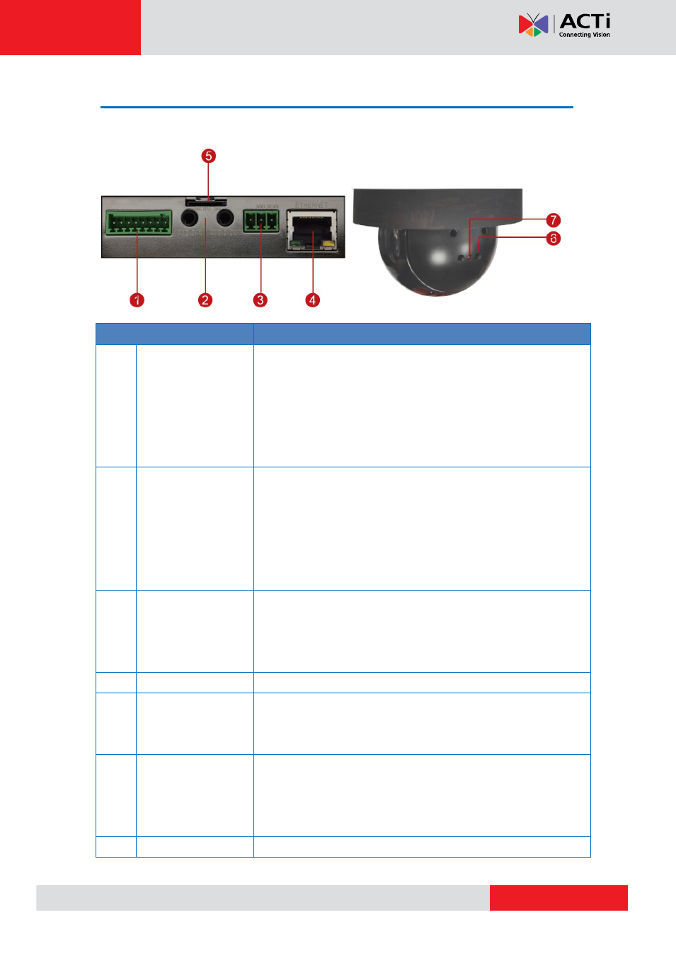
Physical Description
Connectors View
Internal View
Item
Description
1
Digital Input / Output
(DI/DO)
Connects to digital input or output devices, such as an alarm
trigger, panic button, etc. Digital Input (DI) and Digital Output
(DO) devices are used in applications like motion detection,
event triggering, alarm notifications, etc. Please refer to
on page 13 for information on
how to connect DI/DO devices to your camera.
2
Audio IN / Audio
OUT Jacks
The Audio IN jack connects to an audio input device, such as a
microphone with built-in amplifier. The Audio OUT jack connects
to an audio output device, such as a speaker.
NOTE:
Make sure that the connected audio input device has a
built-in amplifier. Connecting an ordinary microphone will dwarf
sounds and will result in inaudible recording.
3
DC 12V Power Input
In case the camera is connected to a non-PoE (Power over
Ethernet) switch, use this connector to connect the camera to an
external power adaptor. See
page 11 for information.
4
Ethernet Port
Connects to a network using a standard Ethernet cable.
5
Memory Card Slot
For local recording, insert a memory card (not included) into the
slot with the metallic contacts facing down the camera.
NOTE:
Supports only microSDHC and microSDXC cards.
6
Reset Button
The Reset Button is used to restore the factory default settings of
the camera, including the administrator’s password. Press and
hold the Reset button for 5 seconds or until the Power LED goes
on page 36.
7
Power LED
The Power LED lights red when the camera is powered up.