8 getting started – Eneo EDMC-3221B User Manual
Page 20
15
• Connecting Alarms
A1,A2,A3,A4 (Alarm Input 1,2,3,4)
You can use external devices to signal the dome camera to react on events. Mechanical or
electrical switches can be wired to the A1,A2,A3,A4 (Alarm Input 1,2,3,4) and G (Ground)
connectors.
See Chapter 3 — Program and Operation for configuring alarm input.
G (Ground)
NOTE: All the connectors marked G or GND are common.
Connect the ground side of the alarm input and/or alarm output to the G (Ground) connector.
AO (5VTTL Alarm Output)
The dome camera can activate external devices such as buzzers or lights. Connect the device
to the AO (Alarm Output) and G (Ground) connectors.
See Chapter 3 — Program and Operation for configuring alarm output.
• Connecting the Power
Connect power of 24VAC or 12VDC 1A for the dome camera.
When using a 12VDC adapter, connect the positive(+) pole to the ‘+’ position and
the negative(-) pole to the ‘-’ position.
Use Certified/Listed Class 2 power source only.
2.8 Getting Started
Once installed apply power to the dome camera. The dome camera will start a configuration
sequence.
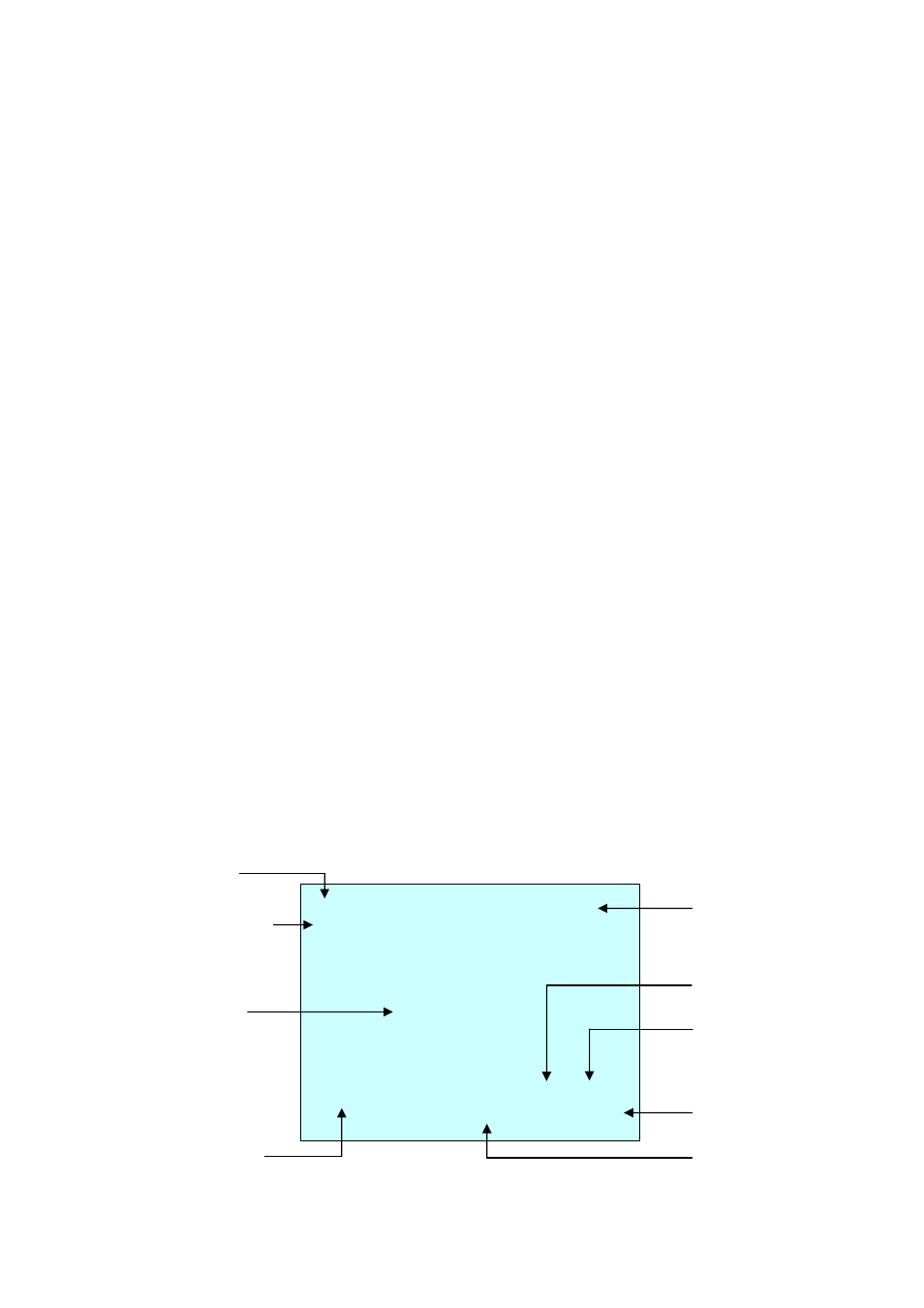
OSD Position
ABC AF AE
001
EMPTY DATA
ALARM:1 DOMEID:001
W→360.0 090.0
INFORMATION
DISPLAY
ALARM DISPLAY
CAMERA TITLE
CAMERA ID
VIEW DIRECTION
PAN & TILT ANGLE
STATUS of
FOCUS and AE
AREA TITLE
FUNCTION TITLE