Installing lpus, Ut 1 in, Figure 23 – H3C Technologies H3C S12500X-AF Series Switches User Manual
Page 27: Ut 2 in, Pivot up the handle of the mpu, Orient the mpu with the upside, Ut 4 in, Push, Ut 5 in, Cont
23
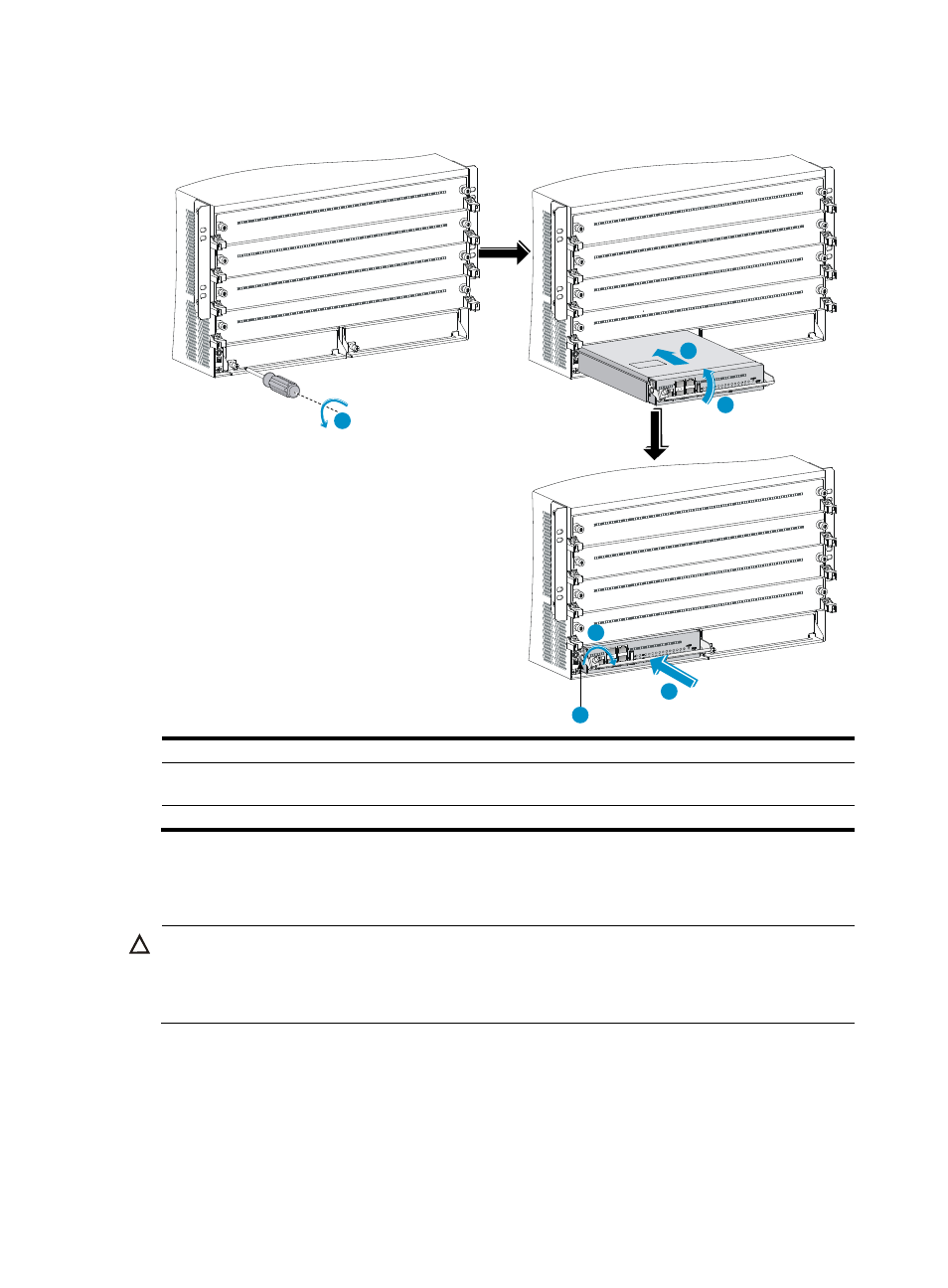
Figure 23 Installing an MPU (S12504X-AF switch)
(1) Loosen the captive screws and remove the filler panel (2) Pivot up the handle
(3) Push the MPU into the slot along the guide rails
(4) Push the MPU until the handle breaks touch the
slot edges tightly
(5) Push the handle until the MPU is secure in position
(6) Fasten the screws
Installing LPUs
CAUTION:
For heat dissipation of the switch, you must install an LPU in the slot where an interface module adapter
is installed. If you are not to install an LPU in the slot, remove the interface module adapter and install a
filler panel.
The S12500-X LPUs with the dimensions 39.8 × 399.2 × 512.1 mm (1.57 × 15.72 × 20.16 in) and
S12500X-AF LPUs with the dimensions 50 x 433 x 524.4 mm (1.97 x 17.05 x 20.65 in) are available
for the switch. An interface module adapter is required when you install an S12500-X LPU on the switch.
3
1
2
5
4
6