Configuration procedure, Verifying the configuration – H3C Technologies H3C S12500 Series Switches User Manual
Page 224
210
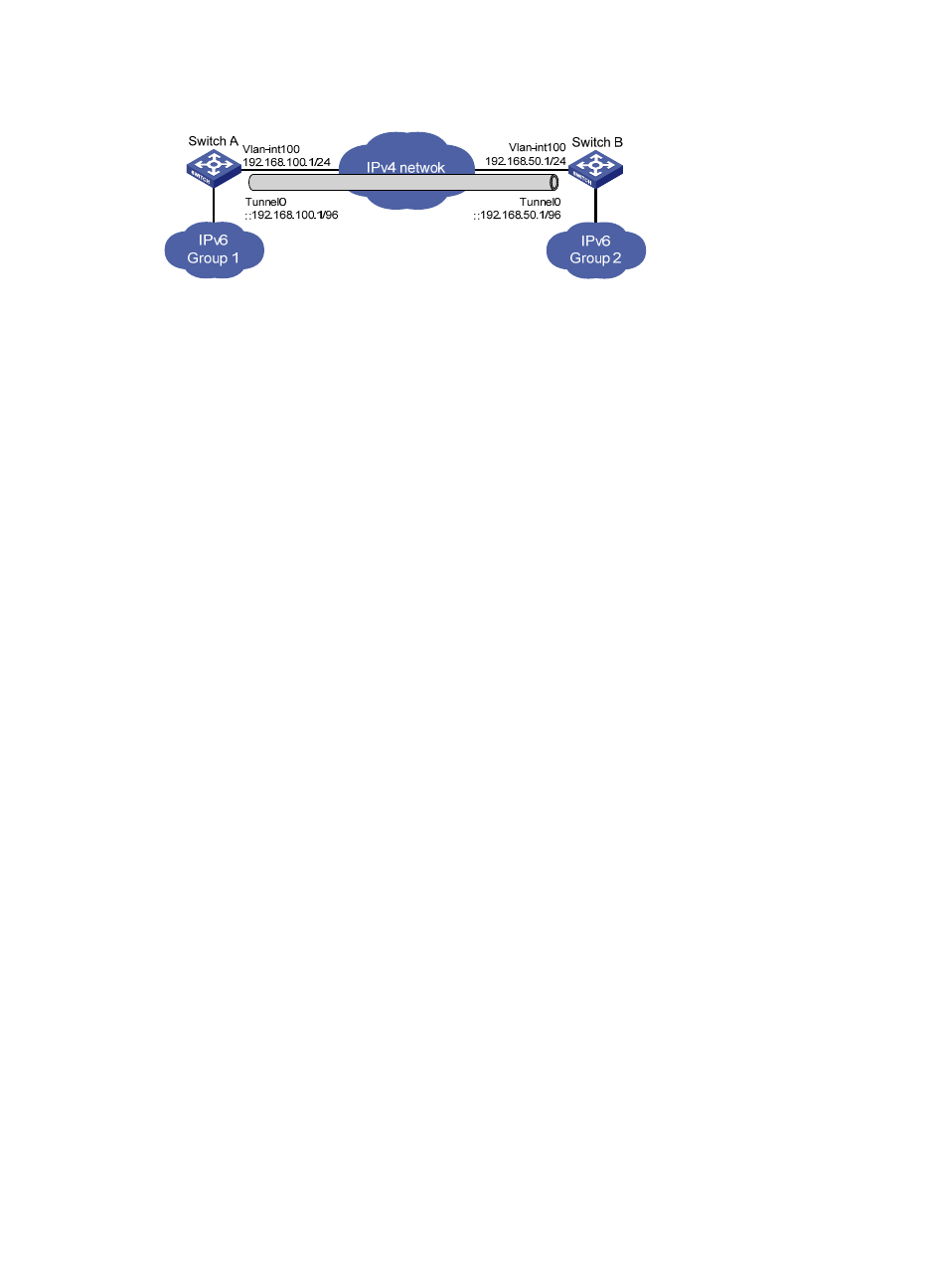
Figure 89 Network diagram
Configuration procedure
Make sure Switch A and Switch B have the corresponding VLAN interfaces created and can reach each
other.
•
Configure Switch A:
# Enable IPv6.
<SwitchA> system-view
[SwitchA] ipv6
# Configure an IPv4 address for VLAN-interface 100.
[SwitchA] interface vlan-interface 100
[SwitchA-Vlan-interface100] ip address 192.168.100.1 255.255.255.0
[SwitchA-Vlan-interface100] quit
# Configure an automatic IPv4-compatible IPv6 tunnel.
[SwitchA] interface tunnel 0
[SwitchA-Tunnel0] ipv6 address ::192.168.100.1/96
[SwitchA-Tunnel0] source vlan-interface 100
[SwitchA-Tunnel0] tunnel-protocol ipv6-ipv4 auto-tunnel
•
Configure Switch B:
# Enable IPv6.
<SwitchB> system-view
[SwitchB] ipv6
# Configure an IPv4 address for VLAN-interface 100.
[SwitchB] interface vlan-interface 100
[SwitchB-Vlan-interface100] ip address 192.168.50.1 255.255.255.0
[SwitchB-Vlan-interface100] quit
# Configure an automatic IPv4-compatible IPv6 tunnel.
[SwitchB] interface tunnel 0
[SwitchB-Tunnel0] ipv6 address ::192.168.50.1/96
[SwitchB-Tunnel0] source vlan-interface 100
[SwitchB-Tunnel0] tunnel-protocol ipv6-ipv4 auto-tunnel
Verifying the configuration
# Display the status of the tunnel interfaces on Switch A and Switch B.
[SwitchA] display ipv6 interface tunnel 0
Tunnel0 current state :UP
Line protocol current state :UP
IPv6 is enabled, link-local address is FE80::C0A8:6401
Global unicast address(es):