Static ip address assignment configuration example, Network requirements, Configuration procedure – H3C Technologies H3C S12500 Series Switches User Manual
Page 65
51
Static IP address assignment configuration example
NOTE:
The device does not support the BOOTP client.
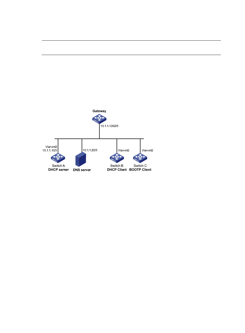
Network requirements
As shown in
, Switch A (DHCP server) assigns a static IP address, DNS server address, and
gateway address to Switch B (DHCP client) and Switch C (BOOTP client) respectively.
The client ID of VLAN-interface 2 on Switch B is 3030-3066-2e65-3234-392e-3830-3530-2d56-6c61-
6e2d-696e-7465-7266-6163-6532. The MAC address of VLAN-interface 2 on Switch C is 000f-e249-
8050.
Figure 27 Network diagram
Configuration procedure
1.
Configure the IP address of VLAN-interface 2 on Switch A:
<SwitchA> system-view
[SwitchA] interface vlan-interface 2
[SwitchA-Vlan-interface2] ip address 10.1.1.1 25
[SwitchA-Vlan-interface2] quit
2.
Configure the DHCP server:
# Enable DHCP.
[SwitchA] dhcp enable
# Enable the DHCP server on VLAN-interface 2.
[SwitchA] interface vlan-interface 2
[SwitchA-Vlan-interface2] dhcp select server global-pool
[SwitchA-Vlan-interface2] quit
# Create DHCP address pool 0, configure a static binding, DNS server and gateway in it.
[SwitchA] dhcp server ip-pool 0
[SwitchA-dhcp-pool-0] static-bind ip-address 10.1.1.5 25
[SwitchA-dhcp-pool-0] static-bind client-identifier
3030-3066-2e65-3234-392e-3830-3530-2d56-6c61-6e2d-696e-7465-7266-6163-6532
[SwitchA-dhcp-pool-0] dns-list 10.1.1.2
[SwitchA-dhcp-pool-0] gateway-list 10.1.1.126