Configuration procedure, Network requirements – H3C Technologies H3C S12500 Series Switches User Manual
Page 30
16
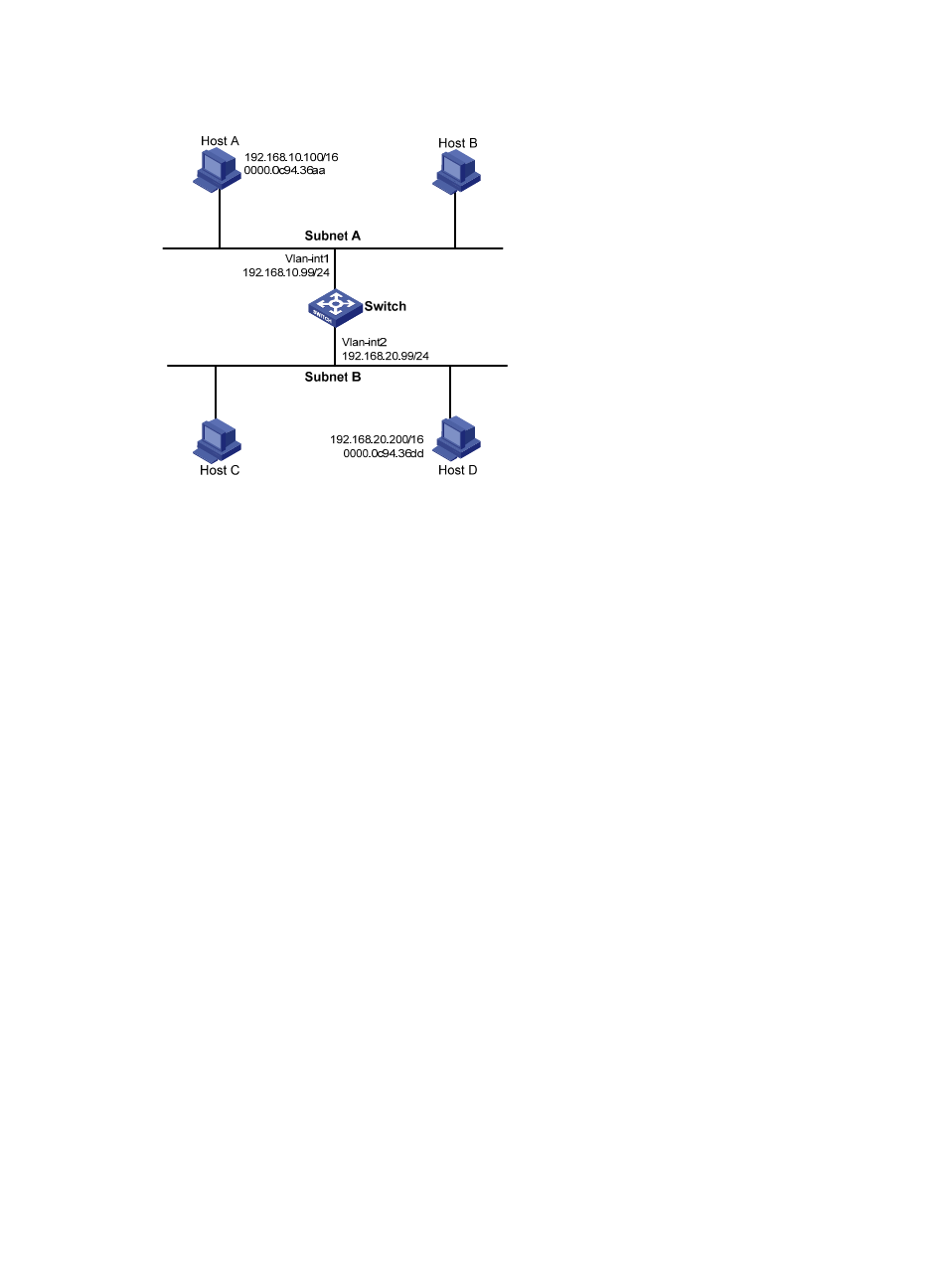
Figure 7 Network diagram
Configuration procedure
# Create VLAN 2.
<Switch> system-view
[Switch] vlan 2
[Switch-vlan2] quit
# Specify the IP address of interface VLAN-interface 1.
[Switch] interface vlan-interface 1
[Switch-Vlan-interface1] ip address 192.168.10.99 255.255.255.0
# Enable proxy ARP on interface VLAN-interface 1.
[Switch-Vlan-interface1] proxy-arp enable
[Switch-Vlan-interface1] quit
# Specify the IP address of interface VLAN-interface 2.
[Switch] interface vlan-interface 2
[Switch-Vlan-interface2] ip address 192.168.20.99 255.255.255.0
# Enable proxy ARP on interface VLAN-interface 2.
[Switch-Vlan-interface2] proxy-arp enable
[Switch-Vlan-interface2] quit
After completing preceding configurations, use the ping command to verify the connectivity between
Host A and Host D.
Local proxy ARP configuration example in case of port isolation
Network requirements
, Host A and Host B belong to the same VLAN, and are connected to
GigabitEthernet 3/0/3 and GigabitEthernet 3/0/1 of Switch B respectively. Switch B is connected to
Switch A through GigabitEthernet 3/0/2. On Switch B, Layer 2 and Layer 3 port isolation are configured