Network requirements, Configuration procedure – H3C Technologies H3C S12500 Series Switches User Manual
Page 32
18
[SwitchA] interface vlan-interface 2
[SwitchA-Vlan-interface2] ip address 192.168.10.100 255.255.0.0
The ping operation from Host A to Host B is unsuccessful because they are isolated at Layer 2.
# Configure local proxy ARP to let Host A and Host B communicate at Layer 3.
[SwitchA-Vlan-interface2] local-proxy-arp enable
The ping operation from Host A to Host B is successful after the configuration.
Local proxy ARP configuration example in super VLAN
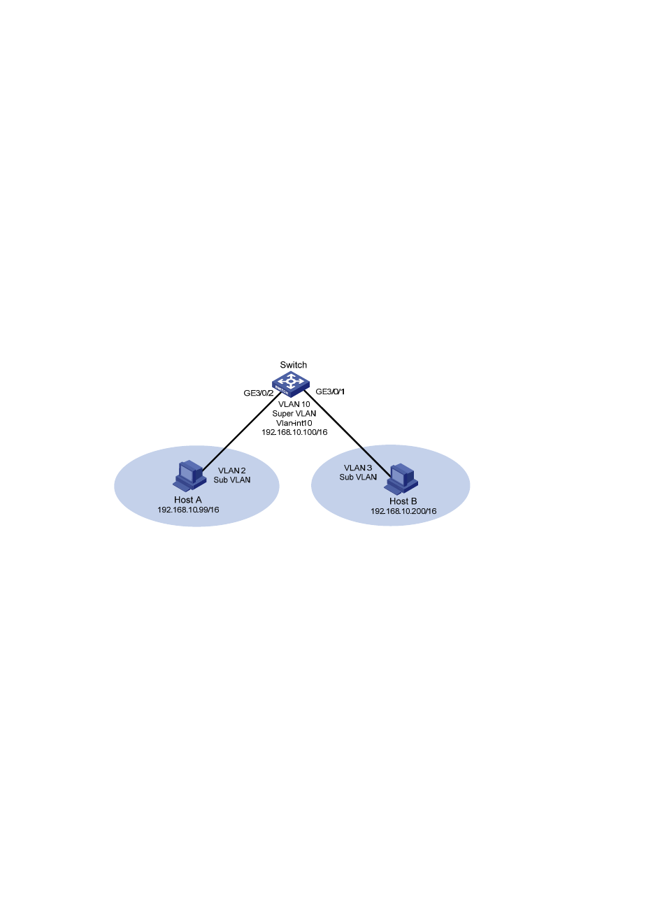
Network requirements
As shown in
, a super VLAN, VLAN 10, is created, with the interface IP address being
192.168.10.100/16. Sub VLANs (VLAN 2 and VLAN 3) are created. GigabitEthernet 3/0/2 belongs to
VLAN 2 and GigabitEthernet 3/0/1 belongs to VLAN 3.
As Host A and Host B belong to different sub VLANs, they are isolated at Layer 2. Configure local proxy
ARP on the switch to implement Layer 3 communication between Host A and Host B.
Figure 9 Network diagram
Configuration procedure
# Create the super VLAN and the sub VLANs. Add GigabitEthernet 3/0/2 to VLAN 2 and
GigabitEthernet 3/0/1 to VLAN 3. Configure the IP address 192.168.10.100/16 for the interface of
VLAN 10.
<Switch> system-view
[Switch] vlan 2
[Switch-vlan2] port gigabitethernet 3/0/2
[Switch-vlan2] quit
[Switch] vlan 3
[Switch-vlan3] port gigabitethernet 3/0/1
[Switch-vlan3] quit
[Switch] vlan 10
[Switch-vlan10] supervlan
[Switch-vlan10] subvlan 2 3
[Switch-vlan10] interface vlan-interface 10
[Switch-Vlan-interface10] ip address 192.168.10.100 255.255.0.0
The ping operation from Host A to Host B is unsuccessful because they are isolated at Layer 2.