Base station rear panel, Rear panel section a - power connector – Grass Valley CopperHead PowerWafer User Manual
Page 23
19
CopperHead PowerWafer
User Guide
Base Station Rear Panel
Fig. 3-6: CopperHead Base Station Back Panel (Dual model shown)
• A: Power Connector (see
Rear Panel Section A - Power Connector
• B: Optical Connectors (see
Rear Panel Section B - Optical Connector
• C: Signal Connectors (see
Rear Panel Section C - Signal Connectors
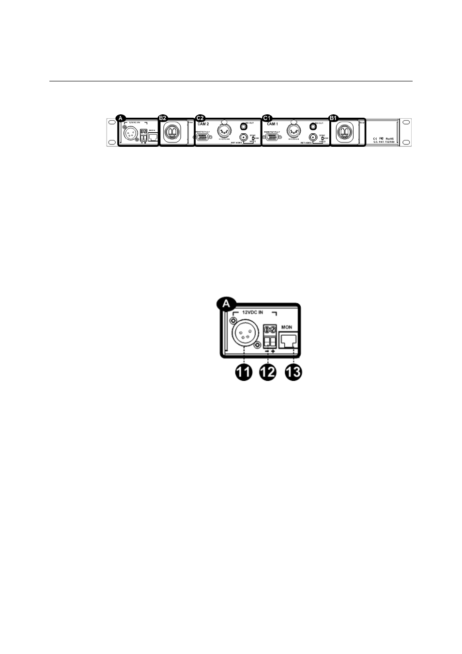
Rear Panel Section A - Power Connector
The CopperHead Base Station can be configured for DC or AC power.
12VDC Power Interface
This power interface is used on CopperHead Base Stations that are not equipped with
internal power supplies. This type of Base Station is typically used with Camera Units
powered locally with a battery or a local power supply at the camera.
Fig. 3-7: 12VDC Power Connector
• 11: 12V DC Power input connector (XLR 4 Pin).
• 12: 12V DC Input - terminal block
This can be used in lieu of the 4-pin XLR or in parallel as a redundant input. See Error!
Reference source not found.for pin-out details
• 13: For Future Use (RJ45)
AC Power Connector Interface
This power interface is used on CopperHead Base Stations that are equipped with an
internal power supply. This type of Base Station is typically used with Camera Units
powered with a PowerWafer via SMPTE Hybrid cable