The control panel, Default button functions, Introduction – Grass Valley CR6400 Family v.1.2 User Manual
Page 20: A thin 2ru control panel, The cp6464, As a warning, If you press it
10
Introduction
The Control Panel
The Control Panel
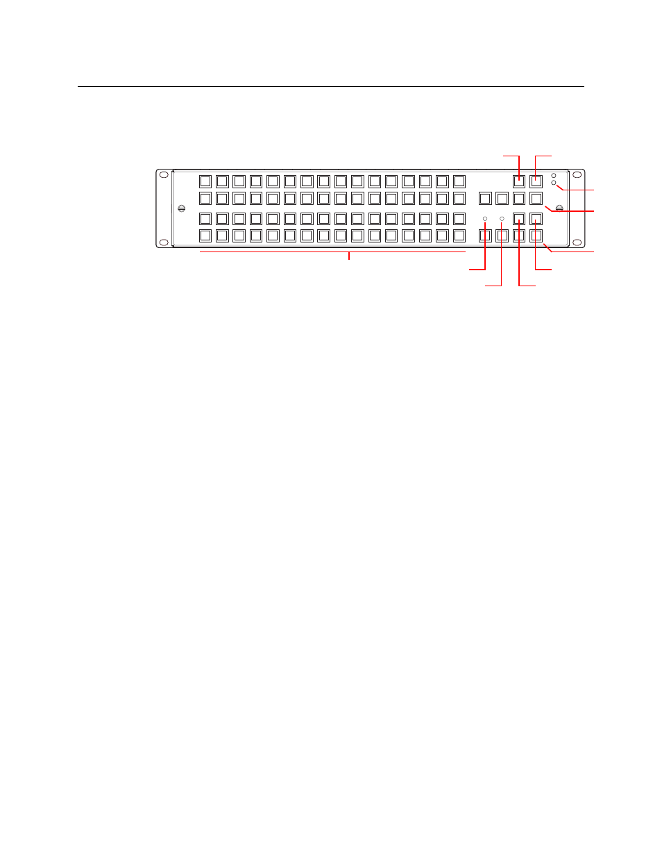
A thin 2RU control panel
—
the CP6464
—
can mount directly on the front of the router as shown
here:
The control panel has an array of 64 device selection buttons at the left and 12 function buttons
at the right. The panel’s default button functions are shown here. The default functions include:
Source Mode
Destination Mode
Source Select
Destination Select
Panel lock
Destination Lock
Level 1–Level 4
In the default function set, four of the buttons are unused.
When a remote panel module is configured in CRSC (Compact Router System Configurator), all
the buttons of the associated panel are configurable and include salvos, which are not available
in the default function set.
Default Button Functions
When coupled with stand-alone routers, the panel has a default button set. These are the
button functions:
•
Level 1–Level 4. These 4 buttons enable switching on (up to) 4 routers in a network. Each
router is considered a level. Typically, levels are used to organize the switching of different
signal types.
In a router network, signals are switched according to which levels are selected using the
level buttons. If a level is unselected, switching on that router is disabled.
If the panel is controlling a single router, and the router’s rotary switch is set to position 1, 2,
3, or 4, the matching level button will be illuminated but disabled because it is not needed.
•
Panel Lock. Prevents accidental use of the entire panel.
The panel lock button, normally low-tally green, goes high tally red when the panel is
locked. All other buttons become disabled until the operator presses the panel lock button
again to unlock the panel.
•
Destination Lock. Prevents takes to one or more destinations.
The destination lock button, normally amber, goes high tally red when the currently selected
destination is locked. When a destination is locked, the destination button turns high tally
red
—
as a warning
—
if you press it.
If you have two or more routers in a network, destinations are locked on selected levels.
A destination button might indicate a lock or might not, depending on the levels the
operator has selected.
7
F
3
B
5
D
9
1
4
C
6
E
2
A
8
0
Power
LEDs
Panel Lock
Dest. Lock
Selection Buttons (64)
Level
(1–4)
Dest. Mode
Source Mode
Unused (4)
Fan LED
Ref. LED