6 checking protective devices, Checking protective devices – SMA SUNNY CENTRAL Maintenance manual User Manual
Page 45
SMA Solar Technology AG
Checking protective devices
Maintenance Manual
SCWAR-WEN094020
45
6 Checking protective devices
Depending on the switch cabinet model and production version, the central inverters have several
circuit breakers which need to be regularly checked for correct function.
You can locate the exact position and the number of circuit breakers using the reference designation
of the components in the provided circuit diagram.
Depending on the switch cabinet model, the following circuit breakers are available:
• Residual current circuit breaker
• Line circuit breaker
• Power switch
• Motor overload switch
6.1 Checking the residual current circuit breaker in the SC 100
The control voltage (supply voltage) is fed to the outside in some Sunny Central inverters in order to
feed external devices, such as COM-B. To protect these devices, these Sunny Central inverters have
residual current breaker. The residual current breaker has a function test button. When pressing this
button, the failure can be simulated.
1. Switch the Sunny Central to "Stop" and open the
doors.
2. Ensure that the Sunny Central is connected to a
control voltage (supply voltage) and is supplied
with power.
3. Tape door contact switch to the "On" position.
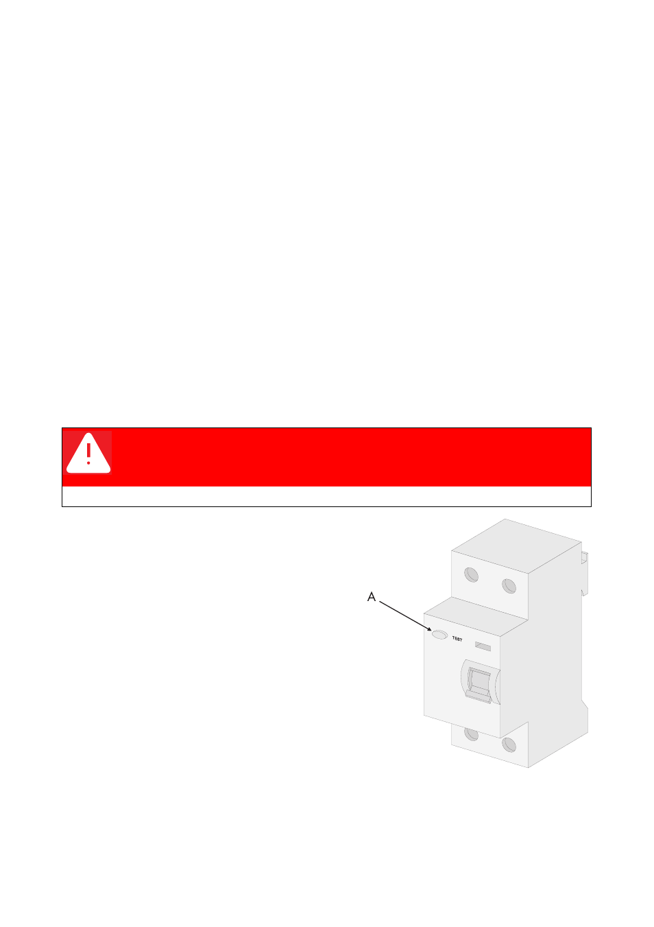
4. Check the residual current breaker by pressing
the function test button (A).
☑ The switch trips.
– The service socket is switched off. Negative-
glow lamp at power outlet switches off.
5. Reconnect the residual current breaker.
6. Release door contact switches (remove the
adhesive tape).
7. Close the cabinet doors.
DANGER!
Death resulting from electric shock and burning upon touching the medium-
voltage grid's live components.
• Do not touch parts other than those described in the instructions.