Option wiring, 5 installation and uninstallation procedure – Yaskawa 1000 Series Drive Option User Manual
Page 31
5 Installation and Uninstallation Procedure
YASKAWA ELECTRIC TOBP C730600 55D 1000-Series Option PS-A10 Installation Manual
31
◆
Option Wiring
1.
Select an external power supply.
When the option is first switched on, two times the normal current will flow through
the option for approximately 0.5 seconds. The option requires at least 3 A to
function properly.
WARNING! Electrical Shock Hazard. Use a battery or a double-reinforced UL Class 2 power supply to
provide power to the option. Using a different type of power supply may result in death or serious injury by
electrical shock or fire.
2.
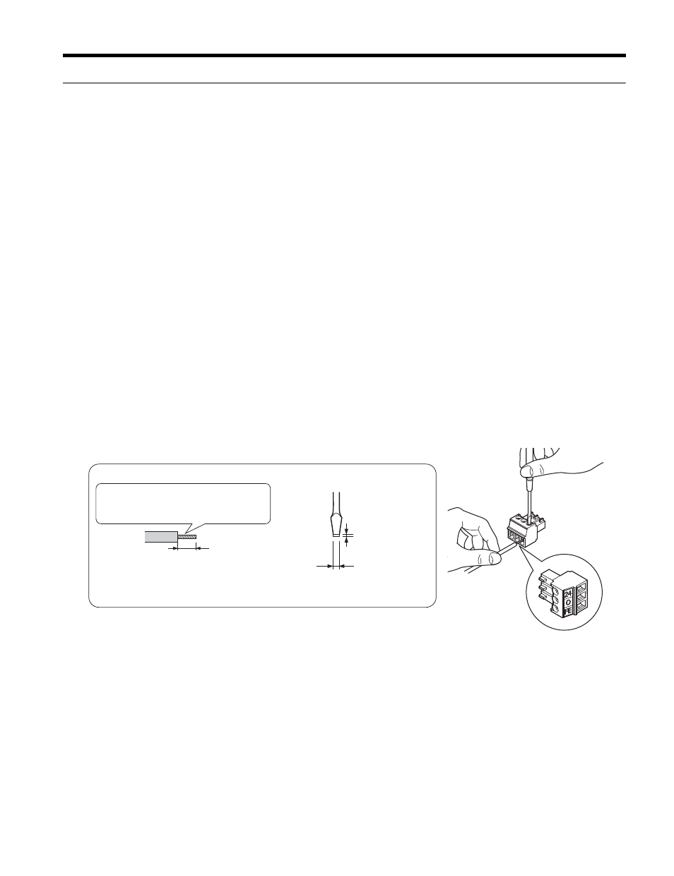
Wire the Terminal Block TB1.
Wire the external power supply to terminal block TB1 on the option.
Use a flat-blade screwdriver to loosen the screws on the option plug, connect wiring
to the 24 V, 0, and FE terminals as shown in
, then tighten the terminal
screws to hold wiring in place.
Refer to Wire Gauges and Tightening Torques on page 32
to confirm that the
proper tightening torque is applied to each terminal. Take particular precaution to
ensure that each wire is properly connected and wire insulation is not accidentally
pinched into electrical terminals.
NOTICE: Be sure to properly connect an external 24 Vdc power source to the power supply plug.
Option Specifications on page 37
for details. Improper wiring practices could damage the option due to
incorrect terminal connections.
Figure 30
Figure 30 Wire the Option Plug
WARNING! Fire Hazard. Tighten terminal screws to the specified tightening torque. Loose electrical
connections could result in death or serious injury by fire due to overheating. Tightening screws beyond the
specified tightening torque may cause erroneous operation, damage the terminal block, or cause a fire.
NOTICE: Heat shrink tubing or electrical tape may be required to ensure that cable shielding does not
contact other wiring. Insufficient insulation may cause a short circuit and damage the option or unit.
Preparing wire ends:
Screwdriver blade size
about 5.5 mm (7/32”)
When not using
crimped insulated
sleeves
Pull back the shielding and lightly
twist the end with fingers, keeping
the ends from fraying.
Blade depth of
0.4 mm or less
Blade width of
2.5 mm or less