5 installation and uninstallation procedure, Wire gauges and tightening torques – Yaskawa 1000 Series Drive Option User Manual
Page 32
5 Installation and Uninstallation Procedure
32
YASKAWA ELECTRIC TOBP C730600 55D 1000-Series Option PS-A10 Installation Manual
■
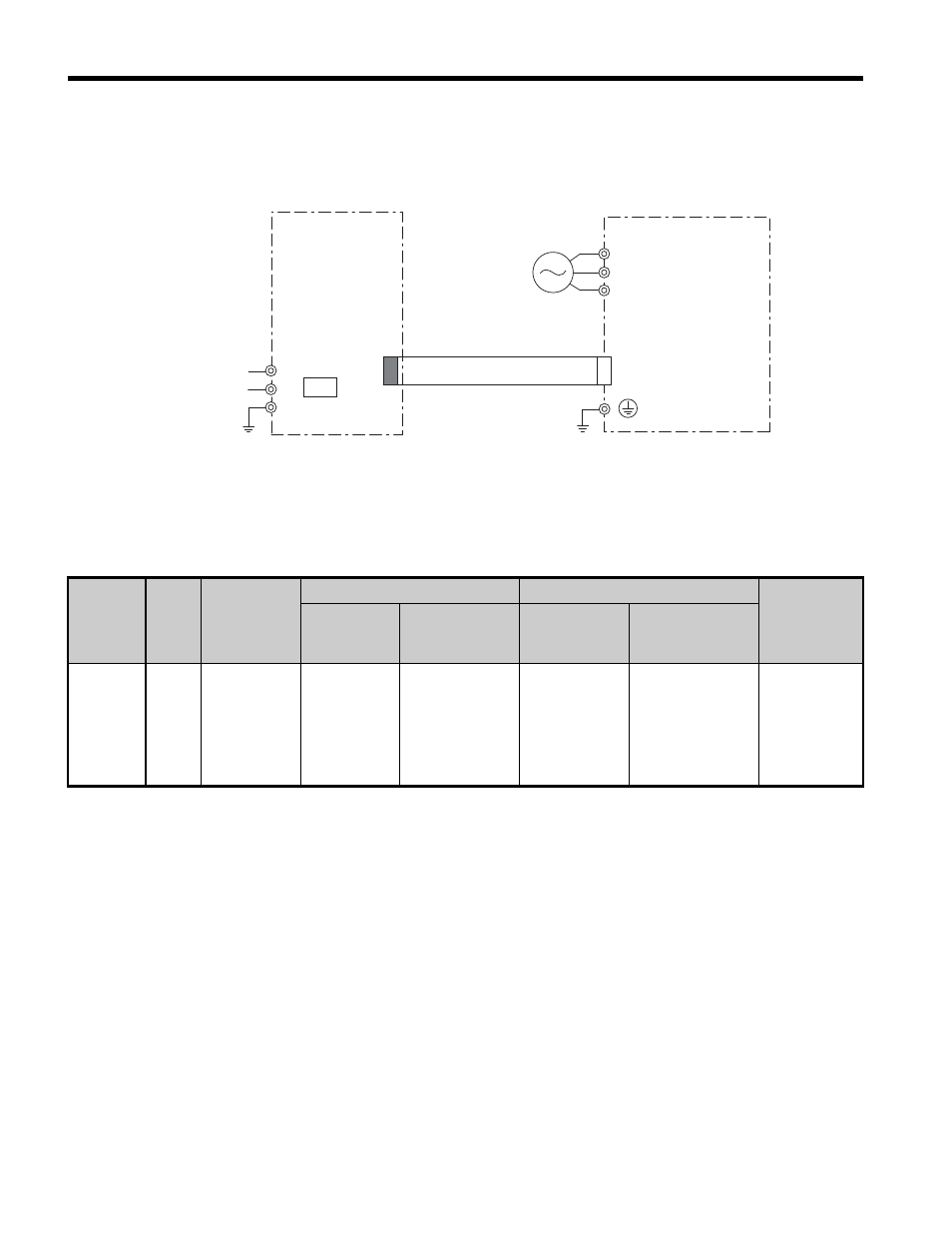
Connection Diagram
illustrates the 24 Vdc Power Supply Option and unit connections.
Figure 31
Figure 31 Connection Diagram for Unit and Option
Note: 24 Vdc external power supply input is supplied by the customer.
■
Wire Gauges and Tightening Torques
Table 4 Wire Gauges and Tightening Torques
Terminal
Number
Screw
Size
Tightening
Torque
Nxm
(inxlb)
Bare Cable
Crimp Terminals
Wire Type
Recomm.
Gauges
mm
2
Applicable
Gauges mm
2
Recomm.
Gauges mm
2
Applicable
Gauges mm
2
24, 0, FE
M2
0.22 to 0.2
(1.95 to 2.21)
0.75
(18 AWG)
Standard wire:
0.25 to 1.0
(24 to 17 AWG)
Single line:
0.25 to 1.5
(24 to 16 AWG)
0.5
(20 AWG)
0.25 to 0.5
(24 to 20 AWG)
Shielded
cable, etc.
R/L1
T/L3
S/L2
AC input
Unit
+
−
FE
24 V
0 V
Option
UL Class 2
24 V Power
Supply Input
CN-1
CN19
TB1