Installation spacing, 3 conditions of acceptability – Yaskawa V1000 Finless Type User Manual
Page 11
3 Conditions of Acceptability
YASKAWA ELECTRIC TOBP C710606 21E YASKAWA AC Drive - V1000 Finless Installation Guide
11
NOTICE: Tighten all screws according to specified torques. Failure to do so may inhibit drive cooling and
possible damage the drive.
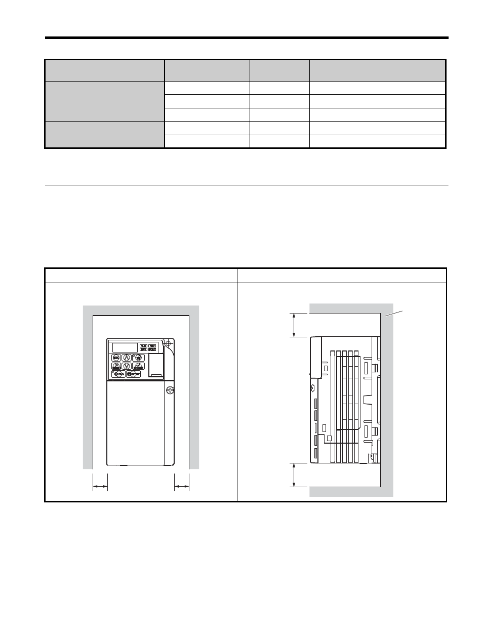
◆
Installation Spacing
illustrates correct installation spacing for proper airflow, and wiring. The drive
should be installed so that the heatsink plate rests flat against the metal back panel to ensure
proper cooling.
Table 4 Correct Installation Spacing
Three-phase 200V class
2A0001 ~ 2A0020
M4
1.0 to 1.3 (0.74 to 0.96)
2A0030 ~ 2A0056
M5
2.0 to 2.5 (1.48 to 1.84)
2A0069
M6
4.0 to 5.0 (2.95 to 3.69)
Three-phase 400V class
4A0001 ~ 4A0011
M4
1.0 to 1.3 (0.74 to 0.96)
4A0018 ~ 4A0038
M5
2.0 to 2.5 (1.48 to 1.84)
Side Clearance
Top/Bottom Clearance
Voltage Class
Model
CIMR-V
Screw Size
Tightening Torque
Nxm (ft-lbf)
a
a
Metal
panel
100 mm
minimum
100 mm
minimum