Yaskawa J7 Drive User Manual
Page 75
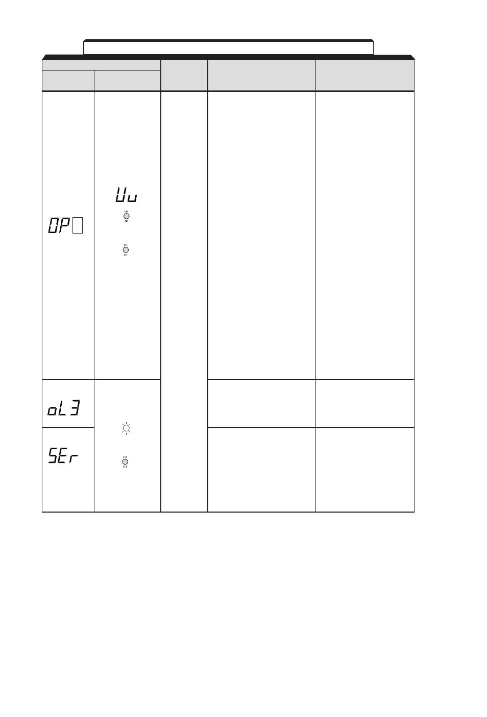
6-2
Alarm Display
Digital
RUN (Green)
Drive
Explanation
Causes and
Operator
ALARM (Red)
Status
Corrective Actions
OP
(Parameter setting
Check the setting values.
error when the parameter
setting is performed
through the MODBUS
communications)
OP1: Two or more values
are set for multi-
function input
selection.
(parameters
n36
to
n39
)
OP2: Relationship among
V / f parameters is not
correct.
(parameters
n09,
n11, n12, n14
)
Blinking
OP3: Setting value of
electronic thermal
standard current
exceeds 150% of
drive rated current.
Warning
(parameter
n32
)
only.
OP4: Upper / lower limit
Fault
of frequency
contacts
reference is reversed.
do not
(parameters
n32
,
change
n33
)
state.
OP5: (parameters
n49
and
n50
)
OP9: Carrier frequency
setting is incorrect.
(parameter
n46
)
OL 3 (Overtorque
Reduce the load, and
detection)
increase the accel / decel
Motor current exceeded
time.
the preset value in
Blinking
parameter
n60
.
SEr (Sequence error)
Check the external circuit
Drive receives
(sequence).
LOCAL / REMOTE select
command or
Blinking
communication / control
circuit terminal changing
signals from the multi-
function terminal while the
drive output is ON.
Table 6-1. Alarm Displays and Corrective Actions - Continued