Connecting the field wiring, Connecting a rain switch sensor – Irritrol IBOC-Plus User Manual
Page 20
18
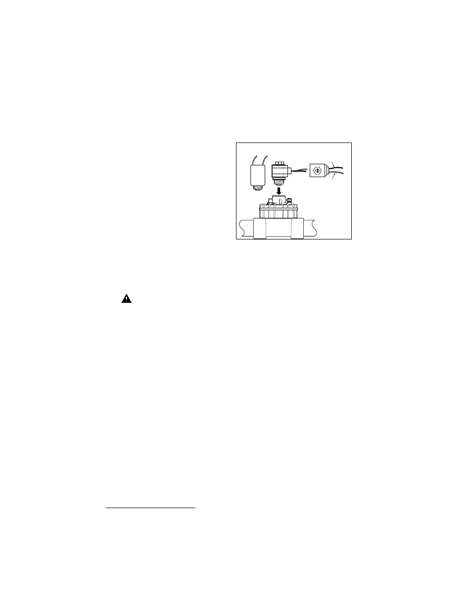
Note: When connecting the DC latching solenoid to the controller,
unlike an AC solenoid which has no specific wiring polarity, the DC
latching solenoid has a power and a common wire. To enable valve
operation, the black wire must be
connected to the valve common and
the red wire to a valve output
terminal. Ensure the solenoid is
assembled with the red and black
wires oriented as shown in Figure 4.
CONNECTING THE
FIELD WIRING
Note: Refer to the recommended
wire size information on page 25.
1. To provide a field common wire, splice one wire to the black wire of
each valve solenoid and optional master valve.
2. Attach a separate control wire to each red valve solenoid wire. Label
the control wires with the intended station number for identification
at the controller.
Caution: All wiring splices must be waterproofed to prevent
short circuits and corrosion.
3. Route all field wires into the controller cabinet through the
2" (52mm) access opening. Remove approximately 1/2" (13mm)
insulation from the ends of each wire.
4. Attach the field common wire to one of the three valve common
terminals labeled “Valve Com.” See Figure 5.
5. Connect each valve control wire to a separate station number
terminal (1-12) and tighten securely. See Figure 5.
6. Connect the Master Valve wire to the terminal labeled MV/Pump.
CONNECTING A RAIN SWITCH SENSOR
The IBOC Plus is designed for use with a normally closed rain sensor
or “Rain Switch.”
Connect a rain switch sensor as follows:
1. Route the two wires from the sensor into the cabinet through the
field wire access opening.
2. Connect the wires to the terminals labeled “Rain Sensor.” See
Figure 5.
Installation Procedures
X
Figure 4
AC Solenoid
DC Latching
Solenoid
(Top View)
Red
Black