Danger, Caution, 4 grounding the inverter – KACO blueplanet 1502xi User Manual
Page 25
blueplanet Operating and Installation Instructions 1502x - 2502x
Page 27
Installation and Start-Up
The GFDI fuse is located on the bottom plate of the inverter.
When a ground fault occurs this fuse will open causing the
inverter to shut down and indicate a fault. Replace only with the
same type and rating fuse. The fuse is a fast-acting 600 V
DC
/ 1 A
KLKD1 (manufacturer: littlefuse) rated device.
The night time start switch is located on the bottom plate of
the inverter. Press and hold the start switch for up to 5 seconds
to wake the inverter when there is no DC input voltage. This
allows the user to display the power that was produced during
that day.
5.4 Grounding the inverter
Grounding must be done according to the NEC (National
Electric Code) and any applicable local electric codes! The
inverter has two sides of grounding we need to consider.
System ground (grounding): connecting the circuit to ground
(i.e. negative of a PV generator, neutral of a split single phase
or bi-polar dc system).
Equipment ground (bonding): Connecting all non-current car-
rying metal parts to ground (array structure, metal enclosure,
module frame)
The AC Grounding Electrode Conductor (GEC) shall be sized
as required by NEC 250.66 and the GEC does not have to be
larger than #6 copper or #4 aluminum if connected to Rod,
Pipe or Plate Electrodes!
The DC Equipment Grounding Conductor (EGC) shall be sized
in accordance with NEC 250.122, if ground fault protection
is used. Otherwise, it should be the same size as the current
carrying conductor!
(A) Grounding single inverters:
For the AC side (system ground) use a continuous irreversibly
appropriately sized conductor bare or insulated conductor
(GEC) to ground the Inverter to the AC GE (Grounding Electrode
- ground rod or in some cases the main water line). If the
ground rod is unavailable, splice irreversibly to the AC GEC.
The DC side (equipment ground) should start at the PV array.
All non-current carrying exposed metal parts of equipment,
raceways, and other enclosures of the PV system shall be
grounded according to NEC 690.43 (e.g. each PV module,
combiner and junction box, metal roofi ng, mounting structure,
DC disconnect, and Inverter). The grounding equipment must
be listed and labeled.
Figure 11: System grounding
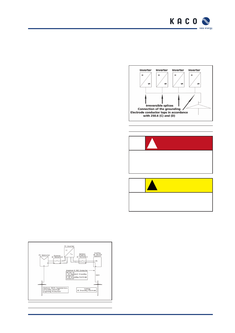
(B) Grounding multiple inverters:
Use a DC GE (Grounding Electrode – ground rod) and run an
appropriately sized conductor from the DC GE to the AC GE.
This will become a GEC for the inverters. Then use a short
appropriately sized conductor jumper to each inverter that is
irreversibly spliced to the GEC.
Figure 12: System grounding-multiple inverters
!
DANGER
To ensure maximum protection against hazardous
contact voltages while assembling photovoltaic
installations, both the positive and the negative
leads must be strictly isolated electrically from the
ground potential (GP).
!
CAUTION
Risk of damage.
Be sure that the polarity is correct when you make
the connection. Connecting it wrongly will cause
damage to the inverter.
The positive or negative connection of the PV generator must
be grounded. To fi nd out which way is correct, ask the module
manufacturer. If there is no preferred grounded connection
by the module manufacturer we recommend grounding the
Negative as this is the most common method.
Connect three strings to the three PV+ clamps and three strings
to the PV- clamps (Figure 13 and Figure 14).