Caution, Installation and start-up – KACO blueplanet 1502xi User Manual
Page 26
Page 28
blueplanet Operating and Installation Instructions 1502x - 2502x
Installation and Start-Up
Positive Grounded System
NOTE
In this confi guration the Positive of the PV generator is
grounded through the GFDI fuse.
DC+
DC+
PV-
2
DC-
PV-
3
DC-
PV+
GFDI
PV-
PV-
1
PV+
3
GFDI
PV+
2
PV+
1
Negative
Positive
Figure 14: DC connection 02x series - Positive
Grounding System
NOTE
A screwdriver (slotted, 3.5 mm) is to be used for the terminals
in the inverter. Put the screwdriver into the intended cut-out.
Press the screwdriver upwards a bit. Put the cable into the
spring terminal. Put the screwdriver back into the original
position. Remove the screwdriver. The spring terminal is
closed and the cable is held in place. Lightly pull on the
wire to be sure it is secure.
!
CAUTION
Be sure the inverter is confi gured for the proper DC
grounding confi guration of the system.
!
CAUTION
The voltage of the solar generator must be
measured before connecting the DC leads to the
inverter terminals. The DC voltage must not exceed
the max. generator voltage because this would
destroy the unit.
Clamp the enclosed cable bridge in the upper GFDI
terminal and the DC+(Figure 13) or DC-connection
(Figure 14). Consult the module manufacturer for infor-
mation on which generator pole should be earthed.
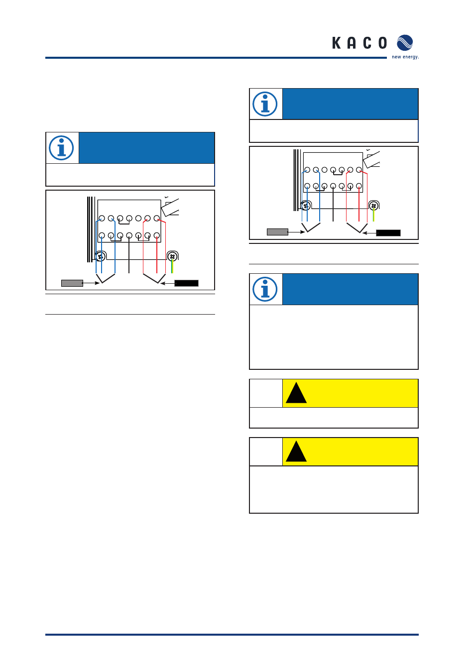
Negative Grounded System (Factory Default)
NOTE
In this confi guration the Negative of the PV generator is
grounded through the GFDI fuse.
DC+
DC+
PV-
2
DC-
PV-
3
DC-
PV+
GFDI
PV-
PV-
1
PV+
3
GFDI
PV+
2
PV+
1
Negative
Positive
Figure 13: DC connection 02x series - Negative
Grounding System