Important, 7 interfaces – KACO blueplanet 1502xi User Manual
Page 31
blueplanet Operating and Installation Instructions 1502x - 2502x
Page 33
Installation and Start-Up
5.7 Interfaces
All interfaces are connected on the communication circuit board.
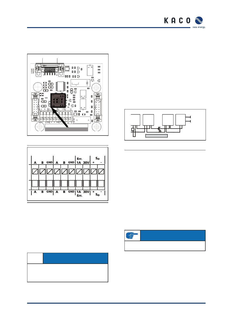
RS485 Termination Switch
Figure 24: Communication circuit board with
highlighted RS485 termination switch
Figure 25: Interface terminals
(A) Connecting the fault signal relay
The inverter is equipped with a potential-free relay contact to
signal faults. This contact closes if a fault occurs. The contact is
designed as a NO contact and marked as “ERR” on the circuit
board. Maximum contact load
•
DC: 30 V / 3 A.
•
AC: 250 V / 1.5 A.
IMPORTANT
In the event of failure of the grid-feed phase (power failure on
the public grid), the relay will not trigger. If this happens, all LEDs
and the display go out. The inverter is shut down completely.
A fault signal cannot be sent.
(B) Connecting the S0 output
The inverter is equipped with an S0 pulse output. Items such
as a large display can be connected to it. The pulse rate is
adjustable (see „5.9 Parameter programming“).
(C) The RS485 interface connection
The connection terminal (Figure 25) is on the blueplanet com-
munication circuit board. To connect several blueplanet invert-
ers, terminal A of one blueplanet is connected to terminal A
of the other blueplanet. Terminal B is connected in the same
manner. A twisted, shielded data cable is required for this. The
connection to the KACO proLOG is established similarly to the
interconnection of inverters. A connection diagram is displayed
in Figure 26. The total length of the RS485 wiring should not
exceed 4,000 feet. Proper polarity must be maintained or
devices will not be able to communicate.
blueplanet
proLOG
AA BB
blueplanet
AA BB
blueplanet
AA BB
AB
DSL or
Ethernet
120V
AC
Max. 32 inverters
Figure 26: Connection diagram for the RS485
interface using the KACO proLOG
In Figure 26, a terminating resistor (R
a
) is connected to the last
inverter in the chain. For proper signal transmission, the last
unit in a chain must have a terminating resistor.
The terminating resistors in the other inverters of the chain
must be deactivated (set to “OFF”). In the last unit of the
chain, switch “1” is set to “ON” and switch “2” is set to “OFF”.
The switch is on the communication circuit board above the
terminal block (Figure 24).
With a bus system such as the RS485, each unit sharing this
bus must possess a unique address, regardless of whether it is
an inverter or any other device. The exception is the monitoring
device which is the master. This unit does not need an address.
For inverters, the address range can be selected between
1 and 32. You can defi ne the address for each inverter using
the confi guration menu (see Operating Instructions).
IMPORTANT
Ensure that the A and B wires are properly connected.
Communication is not possible if the wires are reversed.