Rear panel features, Chapter 1, Introduction – Lanner FW-8771 User Manual
Page 10
5
Introduction
Network Application Platforms
Chapter 1
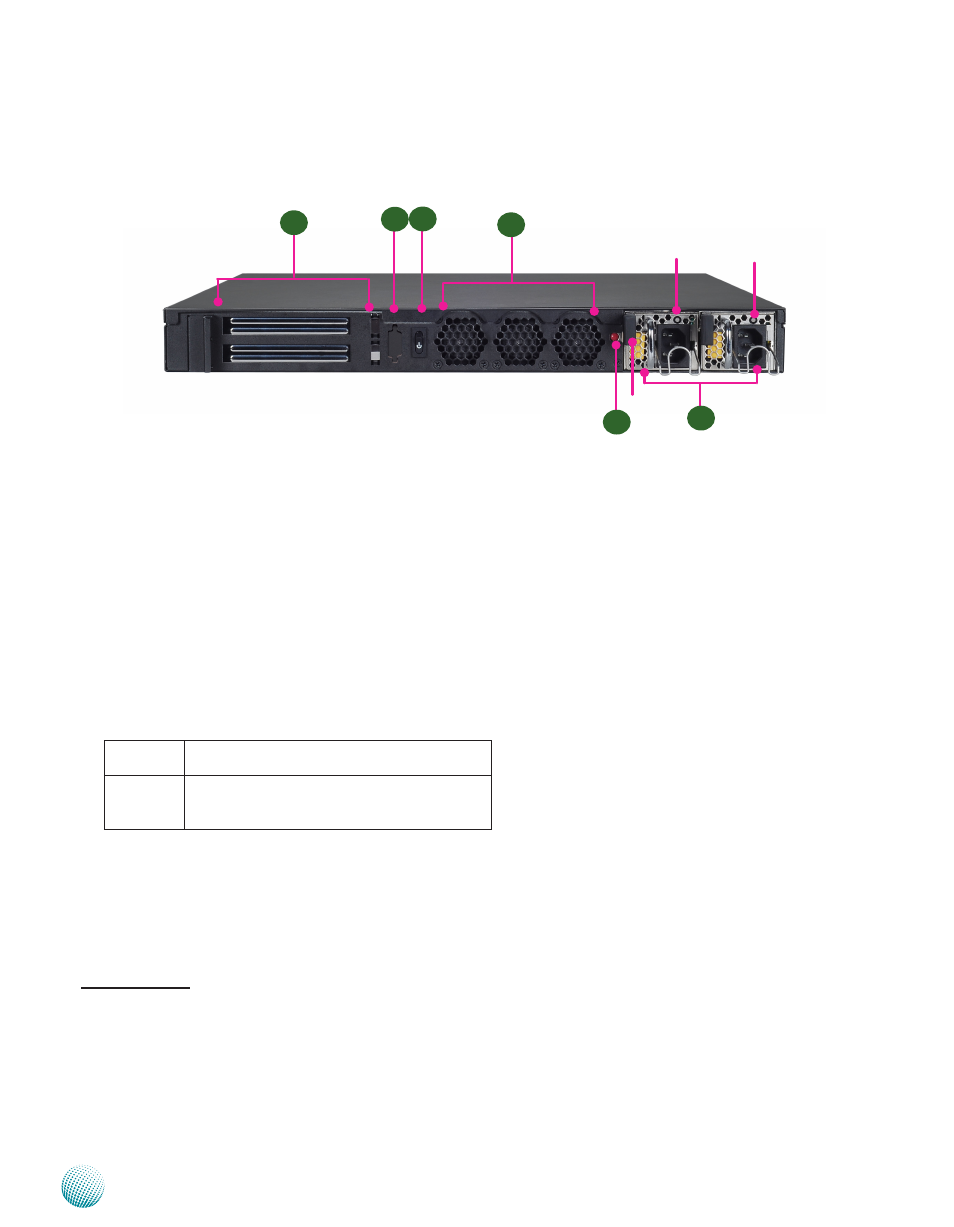
Rear Panel Features
R1
R2
FAN 3 FAN 2 FAN 1
R1 PCIe Expansion Slot (full-height and half-length PCI-E expansion card)
*
R2 VGA port (optional)
R3 Power-on Switch
It is a switch to turn on or off the power.
R4 FAN1~FAN3
These fans have smart fan feature. These fans have smart fan feature which can be turned on automatically when the
temperature exceed the set threshold.
R5 Power Supply (Redundant PSU is also an option)
The redundant power supply is hot-swappable and can be withdrawn and replaced when the alarm sounds. Note the
redundant power supply is only available on some models. See table below for more information.
FW-8771A 8 GbE LAN ports (with 3 pair G3 LAN Bypass),
single PSU, LCM & keypad
FW-8771C 8 GbE LAN ports (with 3 pair G3 LAN Bypass)+
2x NIC module expansion slots, redundant PSU,
LCM & keypad
R6 Redundant Power Supply Alarm Switch
†
When the alarm sounds, press this switch to turn the alarm off and replace the failed power. However, the LED of the
failed power supply will continue flashing.
* This is available for both model FW-8771A and FW-8771C.
† This slot can accommodate both single and redundant power supply unit; for installation guide, refer to the attached
pdf file.
R5
PSU Alarm Switch
R4
R6
PSU latch
PSU LED
PSU LED
R3