Chapter 3, Motherboard information – Lanner FW-8771 User Manual
Page 21
16
Motherboard Information
Network Application Platforms
Chapter 3
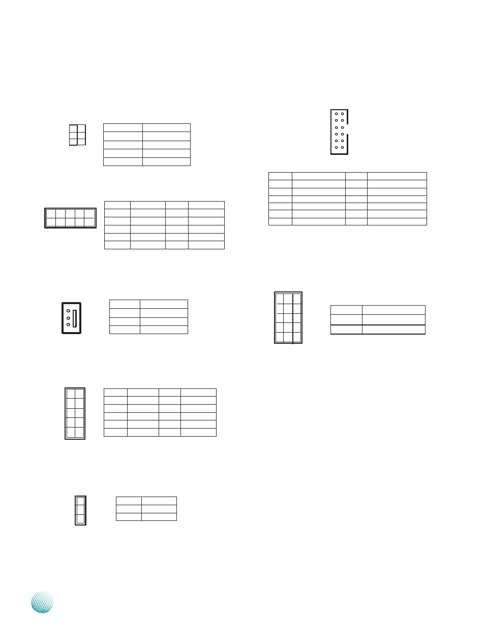
Clear CMOS and Disable ME Jumper Setting (J2): It
is for clearing the CMOS memory and system setup
parameters by erasing the data stored in the CMOS
RAM such as the system passwords.
DIO Port (J14)
PMBUS Pin Headers (PMBUS1)
Gen3 Bypass Pin Headers (J9)
Gen3 Bypass Firmware download Setting (J10)
Pin No.
Function
1-3
ME_DISABLE
3-5
NORMAL
2-4
NORMAL
4-6
CLEAR CMOS
1
3
5
2
4
6
9 1
10 2
Pin No.
Function
1
SMBCLK
2
SMBDAT
3
GND
3
2
1
Pin No.
Function
Pin No.
Function
1
GPO_1
2
GPI_1
3
GPO_2
4
GPI_2
5
GPO_3
6
GPI_3
7
GPO_4
8
GPI_4
9
GND
10
GND
9
1
10
2
Pin No. Function Pin No.
Function
1
KEY
2
KEY
3
RXD
4
RTS
5
TXD
6
CTS
7
KEY
8
KEY
9
GND
10
POWER
Pin No.
Function
1-2
Normal
2-3
Flash
3
2
1
VGA Interface (VGA1): It is for connecting the VGA
interface cable (2X6 pin to female DB15 connector)
Onboard or IPMI VGA Signal Selection (J18): A jumper
to select VGA output between the onboard VGA
connector and the VGA connector on the IPMI card.
11
1
12
2
Pin No.
Function
PIN NO.
Function
1
CRT-R
2
GND
3
CRT-G
4
GND
5
CRT-B
6
GND
7
AHSYNC
8
NC
9
AVSYNC
10
GND
11
DDC_DATA
12
DDC_CLK
Pin No.
Function
1-2
Onboard
2-3
IPMI
1
4
7
10
19
3
6
9
12
21