Kichler 12353BK v.1 User Manual
Kichler Hardware
Kichler
®
leD UNDercABiNeT MOUNT POWer SUPPlY
iNSTAllATiON iNSTrUcTiONS
P/N: 12353BK, 12353Wh
NOTe: All installations should comply with national and
local electrical codes. if you have any doubts concerning
installation contact a qualified licensed electrician.
iMPOrTANT SAFeTY iNSTrUcTiONS
A) Read all instructions.
B) Do not conceal or extend exposed conductors through a
building wall.
C) Do not install this system in wet locations.
D) For low voltage exposed insulated conductor systems required
by 30.1(c) do not install any part of this system less than 7
feet (2.2 m) above the floor.
E) To reduce the risk of fire and burns, do not install this lighting
system where the exposed bare conductors can be shorted
or contact any conductive materials.
F) To reduce the risk of fire and overheating, make sure all
connections are tight.
G) Do not install any luminaire closer than 6 inches (15.25 cm)
from any curtain, or similar combustible materials.
H) Turn off electrical power before modifying the lighting system
in any way.
SAVe TheSe iNSTrUcTiONS
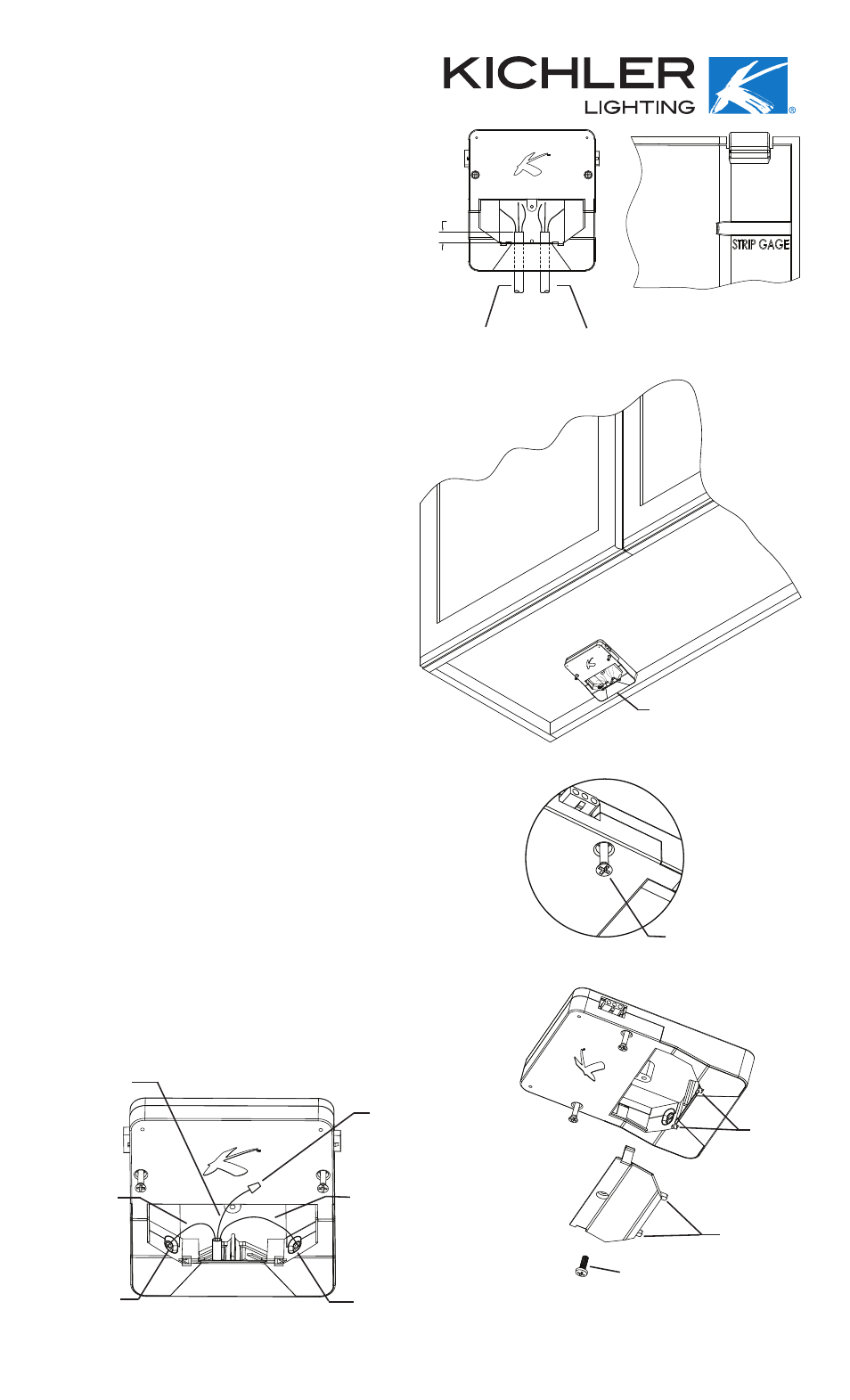
1. On the tall side of wire module there are two gates. Feed a
minimum of 4” (10.2 cm) of Type NM non-metallic sheathed
cable (12-2 with ground or 14-2 with ground) through the gate.
Trim cable to 4” (10.2 cm) if necessary .
NOTe: These gates serve as strain reliefs holding cable
securely in place. Gates should not be removed and no more
then one cable should pass through each.
2. Peel back and remove outer jacket on cable to approximately
½” (1.3 cm) of inside of gate. (See Fig. 1)
3. Strip approximately ½” (1.3 cm) of insulation off each black
and white wire.
NOTe: On inside of wire module cover is a gage to assist in
stripping the correct amount of insulation. (See Fig 2)
4. Position the housing against the back of the cabinet and fasten
the housing to the mounting surface using the captive screws.
(See Fig. 3 and 4)
NOTe: DO NOT OVER TIGHTEN SCREW.
5. Use pliers to push stripped wires into the appropriate connectors.
Careful not to cut insulation. (See Fig. 5)
NOTe: The push-in connectors are surrounded by color
coded rings, indicating which wire to install.
• black wire to black ring connector
• white wire to white ring connector
NOTe: To remove the wires from the connectors, trim wires
close to connector. Grip the trimmed stub with pliers and
twist while pulling out ward.
6. Push the un-insulated ground wire(s) into the provided, loose
splicing connector. (See Fig. 5)
7. Slightly tug on each wire to ensure connection has been
made and is secure.
8. Install wire module cover over exposed wires by aligning
the front tabs with the slots in the housing and snapping cover
into place. Firmly fasten the cover to the housing by using the
included screw. (See Fig. 6)
NOTe: DO NOT OVER TIGHTEN SCREW.
9. At this time proceed to LED fixture installation following
instructions provided with fixture.
10. To remove cover, remove center screw then slide screwdriver
into slot formed by cover and wire module then pull screw
driver handle away from wire module until cover separates
from wire module.
Date Issued: 12/5/08
IS-12353-CB
1/2"
FIG. 1
FIG. 2
FIG. 3
50W POWER SUPPLY
PRE-INSTALLED SCREW
FIG. 4
SPLICING CONNECTOR
BLACK WIRE
BLACK RING
CONNECTOR
WHITE WIRE
WHITE RING
CONNECTOR
GROUND WIRE
SLOTS IN
HOUSING
TABS ON COVER
SCREW
FIG. 6
FIG. 5
FROM SWITCH OR
MAIN BREAKER
TO NEXT RUN OR
CABINET
INSTRUCTIONS
For Assembling and Installing Fixtures in Canada
Pour L’assemblage et L’installation Au Canada