Kichler 12380 User Manual
Kichler Hardware
Before Installing:
All installations should comply with National and local electrical codes.
If you have any doubts concerning installation contact a qualified licensed electrician.
IMPORTANT SAFETY INSTRUCTIONS
a) Read all instructions
b) Do not conceal or extend exposed conductors through a building wall.
c) Do not install this system in damp or wet locations.
d) To reduce the risk of fire and burns, do not install this lighting system where the exposed bare conductors can be shorted or contact
any conductive materials.
e) To reduce the risk of fire and overheating, make sure all connections are tight.
f) Do not install any luminaire closer than 6 inches (15.25cm) from any curtain, or similar combustible materials.
g) Turn off electrical power before modifying the lighting system in any way.
SAVE THESE INSTRUCTIONS
PLEASE NOTE: Item 12380BK is suitable for the following surface mount options:
1. The enclosure can be mounted to the surface of a wall.
2. The enclosure can be surface mounted inside a cabinet. The minimum cabinet width is 24”.
3. The enclosure can be vertically surface mounted to the side of a ceiling joist.
1. For use only with Kichler
®
LED 24VDC Class 2, 5 AMP MAX Cabinet Lighting fixtures and Accessories.
2. Turn off power.
3. Determine desired location for mounting transformer. Power supply should be located within 25’ of first LED fixture. NOTE: When deciding
location for mounting consideration should be taken for the requirements listed above.
4. Secure power supply enclosure using provided mounting template and mounting screws. Use all four (4) mounting screws, securing into
wall studs if possible, otherwise, use appropriate anchors rated for proper wall material and hanging weight (not included).
5. The Kichler 100 watt power pack has two distinct sections in the enclosure for line voltage and low voltage. It is important to keep the line
voltage and the low voltage wires separate.
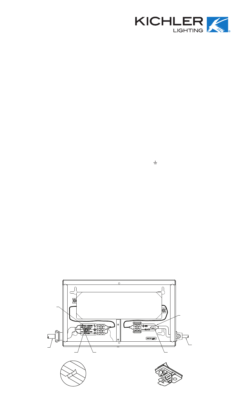
6. Using the pre-punched knock-outs in the metal enclosure, route and connect the 120V line voltage to the primary side of the power supply
using the labeled installed screw terminals, connect the 120V line wire to the terminal marked “L” connect the 120V neutral wire to the
terminal marked “N” and connect the 120V ground wire to the terminal marked with ground ( ). Tighten the corresponding screw on the
terminal block face until wire is secure. See fig. 1.
NOTE: A proper UL listed cable connector must be used in the knock-outs to provide strain relief and wire protection.
7. Maximum number of fixtures connected to each 100 watt power supply should be equal or less than the 100 watt power supply rating.
NOTE: After determining the layout of the system, add the wattage of each system component together to calculate the total system
consumption. The component wattages are marked on the products themselves. The calculated total system consumption should
be equal or less than the 24VDC Class 2 power supply rating that is being used.
8. The Kichler KCL LED system fixtures can have power connected from either end of the fixture, one side has a male connector and the other
side has a female connector. Determine which polarity end, male or female, of your installed fixture run will be needed to connect power.
9. Using the 25’ foot power cable Kichler P/N 12344WH/BK. One side of the interconnect cable has a male connector and the other side has a
female connector. Verify which end you will need to make the power connection to your first fixture.
10. Connect the supplied power connector cable to the first fixture and hold the cable up to mounting surface to estimate the length needed to
reach your remote mounted power supply enclosure. Trim the interconnect cable to the appropriate length for your installation removing the
unused connector on the power cable.
11. Hold the power cable to mounting surface and determine best path for cable. If the cable is being run from cabinet to cabinet a notch such
as a “V” could be cut in cabinet side panels to help keep cable out of sight. See fig. 2.
NOTE: Interconnect cable is UL rated CL2. Installer should check with local building codes to determine if CL2 wire is allowed to run
through walls and ceilings.
12. Peel backing off retaining clip(s) and affix to desired location(s). Surface should be as clean as possible. Drive pre-installed screw into the
cabinet surface to secure the retaining clip to the surface. See fig. 3.
13. Slip Cable into clip(s) and snap closed
14. Insert trimmed end of power cable through a pre-punched knock-out.
NOTE: A proper UL listed cable connector (provided) must be used in the knock-outs to provide strain relief and wire protection.
15. Carefully strip the outer jacket from the red and black power supply wires.
16. Strip ¼” of the insulation from the red and black wires and connect to the secondary 24 volt dc side of the power supply using the installed
screw terminals in the power supply enclosure.
NOTE: THE RED WIRE FROM THE POWER SUPPLY MUST CONNECT TO THE RED WIRE OF THE POWER CABLE AND THE BLACK
WIRE FROM THE POWER SUPPLY MUST CONNECT TO THE BLACK WIRE OF THE POWER CABLE. IF THE SYSTEM DOES NOT
OPERATE, DOUBLE CHECK THAT THESE WIRES ARE CORRECTLY ATTACHED. TWO POWER SUPPLY CABLES CAN BE CONNECTED
TO ONE TERMINAL BLOCK, IF REQUIRED.
120V LINE WIRE
CABLE DE LÍNEA DE 120V
120V LINE VOLTAGE
TENSIÓN DE LÍNEA DE 120V
120V NEUTRAL WIRE
CABLE NEUTRO DE 120V
120V GROUND WIRE
CONDUCTOR DE TIERRA DE 120V
BLACK WIRE
CABLE NEGRO
KICHLER P/N 12344BK/WH
CABLE DE ALIMENTACIÓN DE 24VCC
24VDC POWER CABLE
RED WIRE
CABLE ROJO
FIG. 1
FIG. 2
FIG. 3
Date Issued: 3/16/12
IS-12380-US
KICHLER
®
DESIGN PRO 100W POWER SUPPLY
INSTALLATION INSTRUCTIONS
12380BK