Kichler 12531 v.1 User Manual
Important safety instructions, Save these instructions
This instruction sheet covers the installation of the following Kichler Transformers: 12531BK, 12533BK and 12534BK. Read these instructions
carefully before installing this unit.
BEFORE INSTALLING:
All installations must comply with National and local electrical codes. If you have any doubts concerning installation contact a qualified licensed
electrician.
IMPORTANT SAFETY INSTRUCTIONS
• Read all instructions
• Do not conceal or extend exposed conductors through a building wall.
• Do not install this system in damp or wet locations.
• To reduce the risk of fire and burns, do not install this lighting system where the exposed bare conductors can be shorted or
contact any conductive materials.
• To reduce the risk of fire and overheating, make sure all connections are tight.
• Do not install any luminaire closer than 6 inches (15.25cm) from any curtain, or similar combustible materials.
• Turn off electrical power before modifying the lighting system in any way.
SAVE THESE INSTRUCTIONS
1. For use only with Kichler 12V Xenon Bright Discs Cabinet Lighting fixtures.
2. Turn off power.
3. Determine desired location for mounting transformer. NOTE: When deciding
location for mounting consideration should be taken for the requirements
listed above.
4. Mark the position of the three mounting holes.
5. If mounting to a solid wall surface such as wood:
a)
Drill 1/8 inch (3mm) diameter pilot holes at position marked in step 2.
b)
Align the power unit’s mounting holes with the pilot holes.
c)
Drive screws into the holes.
If mounting to a drywall wall surface:
a)
Drill 1/4 inch (6mm) diameter pilot holes at position marked in step 2.
b)
Push plastic anchors into holes and tap flush.
c)
Align the power unit’s mounting holes with the anchors.
d)
Drive screws into the anchors.
6. The power units have two distinct sections in the enclosure for line voltage
and low voltage. It is important to keep the line voltage and the low voltage
wires separate.
7. If installing 12531BK: Using the pre-punched knock-outs in the metal
enclosure, route and connect the 120V line voltage to the primary side
of the power supply using wire nuts, connect the 120V “hot” wire to the
black wire, connect the 120V “common” wire to the white wire, and
connect the 120V ground wire to the green and yellow wire.
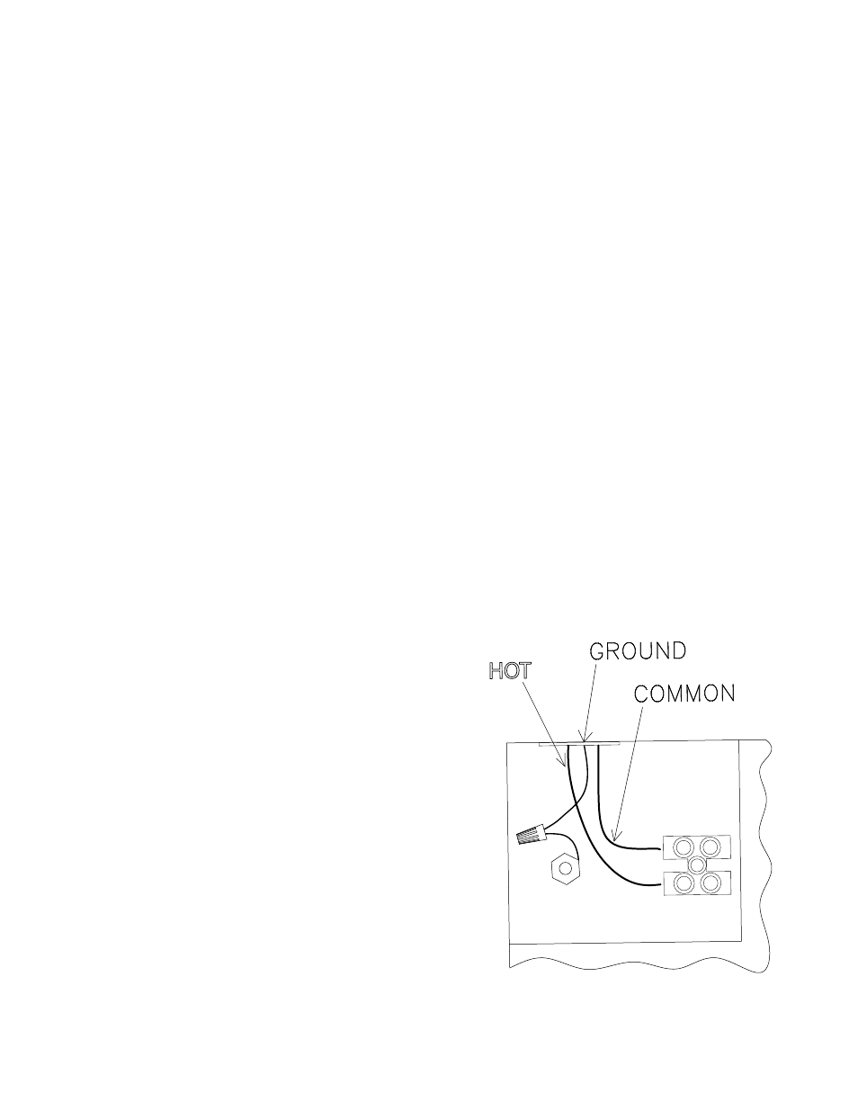
If installing 12533BK or 12535BK: Using the pre-punched knock-outs
in the metal enclosure, route and connect the 120V line voltage to the
primary side of the power supply using the installed screw terminals, connect
the 120V “hot” wire to the lower terminal, connect the 120V “common” wire
to the upper terminal, and connect the 120V ground wire to the green and
yellow wire using a wire nut. Tighten the corresponding screw on the terminal
block face until wire is secure. See fig. 1.
NOTE: A proper UL listed connector must be used in the knock-outs
to provide strain relief and wire protection.
8. Maximum number of fixtures per run should be equal or less than the
maximum power supply wattage rating.
FINDING TRANSFORMER LOAD: Low voltage systems require the
use of a transformer to reduce standard 120-VOLT power from your home
to 12-VOLTS. To determine the transformer size you will need to add
up the wattages of all lamps you plan to use. Select a transformer that
matches as closely as possible to the total lamp wattage without exceeding
the maximum rating. For example, if you have 14 fixtures all rated
at 20 watts, you will need a 360-Watt (VA) transformer (14 x 20 = 280 watts).
Generally, the total lamp load should not be less than one-third the
transformers wattage rating, nor exceed its maximum wattage capacity.
If your total wattage is too high, either divide the load between two
transformers, or use a more powerful transformer.
9. Holding the fixture wire to mounting surface along the determined best
path for the wire to the power unit, estimate the length needed to reach
your remote mounted power supply enclosure. Trim the fixture wire to the
appropriate length for your installation.
10. Secure wire in between power unit and fixture using only insulated staples
or plastic clips.
11. Insert end of fixture wire through a pre-punched knock-out.
NOTE: A proper UL listed bushing or grommet must be used in the knock-
out to prevent abrasion of the wire against enclosure edge.
12. Strip ¼” of the insulation from white fixture wires and connect to the blue
wires of the secondary 12 volt (AC) side of the power supply in the enclosure
using wire nuts.
NOTE: FOR INSTALATIONS USING 12533BK AND 12535BK: THE TOTAL
WATTAGE DRAW FROM EACH OUTPUT TERMINATION CANNOT EXCEED
60W. DO NOT INTERECONNECT THE OUTPUT TERMINATIONS
Date Issued: 12/17/10
IS-12531-CB
HOT
FIG. 1
INSTRUCTIONS
For Assembling and Installing Fixtures in Canada
Pour L’assemblage et L’installation Au Canada