Kichler 15688 User Manual
Kichler Hardware
SAFETY INSTRUCTIONS
REAd ThIS FIRST
kEEp ThESE INSTRUCTIONS
This fixture is intended for installation in accordance with the National
Electric Code (NEC) and Local code specifications. Failure to adhere
to these codes and instructions may result in serious injury and/or
property damage and will void the warranty.
1)
WARNING: This fixture is not to be installed within 10 feet (3M) of a
pool, spa or fountain.
2) This fixture is to be used only with a power unit (transformer) rated a
maximum of 300 W (25 AMPS) 15 volts.
3) The #18 ga. fixture wire is not intended for direct burial.
4) Direct burial rated wire is to be buried a minimum of 6” (152mm)
beneath the surface of the ground.
NOTE: If additional Direct Burial wire is needed, contact your local
Kichler
®
landscape distributor.
• 8 GA wire can be purchased in length of 250’ (76 M), 15503-BK.
• 10 GA wire can be purchased in length of 250’ (76 M), 15504-BK.
• 12 GA wire can be purchased in lengths of 100’ (30 M), 15501-BK;
250’ (76 M), 15502-BK; 500’ (152M), 15505-BK; and 1000’ (304 M),
15506-BK.
5) Fixture shall not use a tungsten halogen lamp unless the fixture is
marked for use with such lamps.
6) Wiring connections must be made with approved/listed wire connection
device(s) suitable for the application. Do not exceed manufacturers’
wiring combination specifications for size and quantity of conductors.
CAUTION
WHEN INSTALLING KICHLER LANDSCAPE LIGHTING (LINE VOLTAGE OR LOW
VOLTAGE), CARE SHOULD BE TAKEN TO KEEP CLEAR OF POTENTIALLY COMBUS-
TIBLE MATERIALS.
WHEN MAINTAINING THE FIXTURES, BE SURE TO REMOVE LEAVES, PINE
NEEDLES, GRASS CLIPPINGS, MULCH, OR ANY DEBRIS THAT HAS ACCUMULATED
ON THE LIGHT BULB, LENS, OR BODY OF THE FIXTURE.
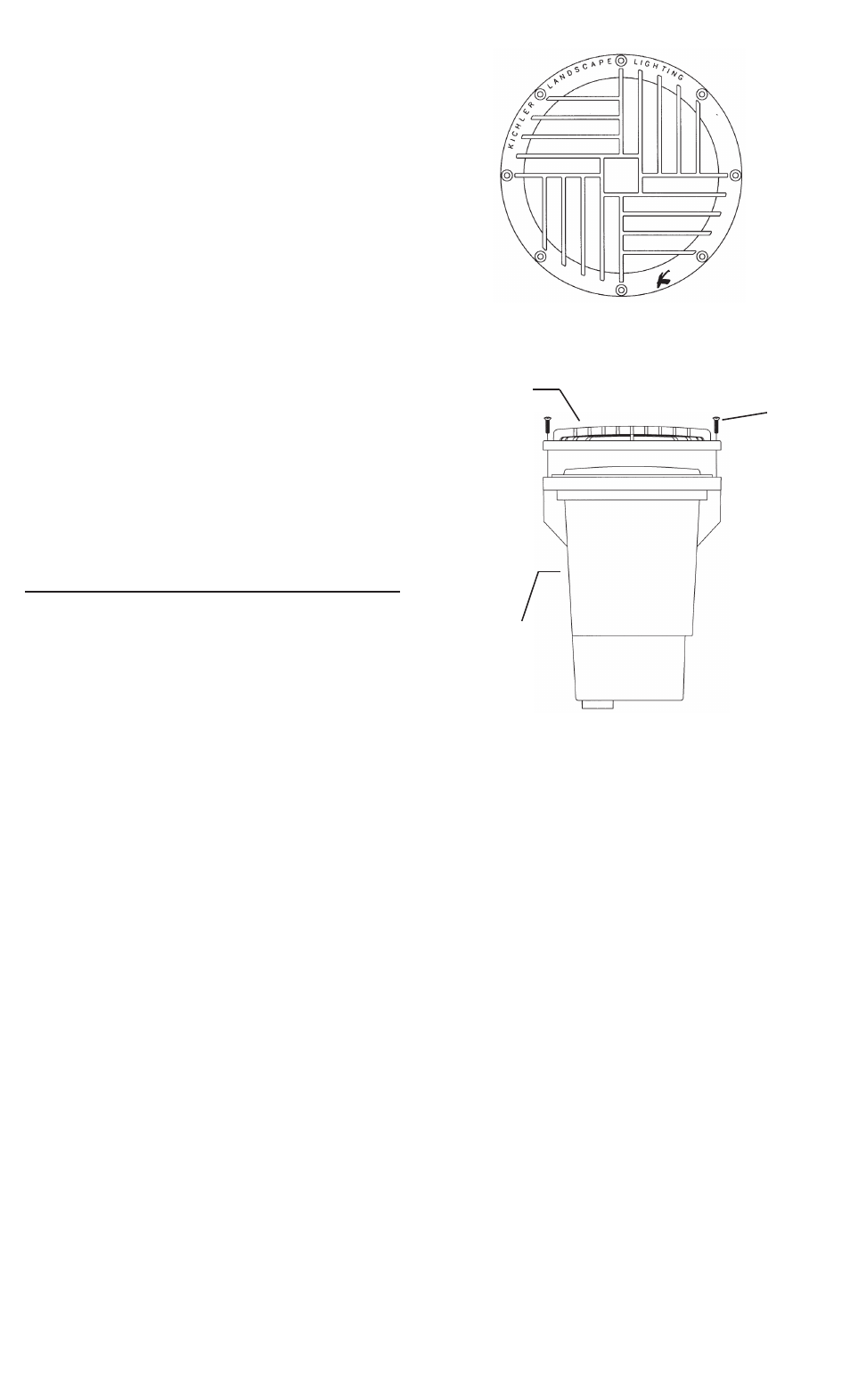
1) Remove existing retaining ring and screws from well light.
2) Insure that all gasket seating surfaces and screw holes are free and
clear of debris. If screw holes are not clear blow debris out or clear with
#10-32 tap.
3) Slip screws previously removed in Step 1 through holes in rock guard.
4) Align screws with holes in well light and tighten using an alternative
torque sequence at 20-30 inch-lbs.
(SEE ILLUST. - NUMBERS
INdICATE ORdER IN WhICh TO TIGhTEN SCREWS.)
INSTRUCCIONES dE SEGURIdAd
pRIMERO LEA ESTO
GUARdE ESTAS INSTRUCCIONES
Este artefacto se debe instalar de acuerdo con el Código Eléctrico
Nacional (NEC, por sus siglas en inglés) y con las especificaciones del
código local. No cumplir con estos códigos e instrucciones puede
resultar en lesiones graves y/ o en daños a la propiedad y anulará la
garantía.
1) Advertenciaertencia: Este artefacto no debe instalarse a menos de
10 pies (3 m) de una piscina (alberca), spa o fuente.
2) Este artefacto debe utilizarse solamente con una unidad de potencia
(tranformador) con capacidad nominal máxima de 300 vatios (25 amp.)
15 voltios.
3) El alambre del artefacto calibre No. 18 no es para soterrado directo.
4) El alambre clasificado para soterrado directo se debe enterrar un
mínimo de 6 pulgadas (152 mm) debajo de la superficie del terreno.
NOTA: Si necesita alambre de soterrado directo adicional, comuníquese
con su distribuidor local Kichler® de productos de jardinería ornamental.
• El alambre calibre 8 puede comprarse en longitud de 250’ (76 m.),
15503-BK
• El alambre calibre 10 puede comprarse en longitud de 250’ (76 m.),
15504-BK
• El alambre calibre 12 puede comprarse en longitudes de 75’ (22 m.),
15550-BK; 100’ (30 m.), 15501-BK; 250’ (76 m.), 15502-BK; 500’ (152 m.),
15505-BK; y 1000’ (304 m.), 15506-BK.
5) El artefacto no debe utilizarse con lámparas de halógeno, a menoss
que el artefacto esté marcado para usar con tales lámparas.
6) Las conexiones de cableado se deben hacer con las conexiones
del(los) dispositivos) de conexión de cableado aprobados/ de la lista,
adecuados para la aplicación. No exceda las especificaciones de
combinación de cableado del fabricante para el tamaño y cantidad de
conductores.
WARRANTY
WE WARRANT THE LANDSCAPE PRODUCTS FEATURED IN OUR LANDSCAPE LIGHTING CATALOG (WITH THE EXCEPTION OF LIGHT BULBS) FOR FIVE YEARS AGAINST DEFECTS IN
MATERIALS AND WORKMANSHIP IF IT WAS PROPERLY INSTALLED AND FAILED UNDER NORMAL OPERATING CONDITIONS, PROVIDED IT IS RETURNED TO THE POINT OF PURCHASE,
WHERE IT WILL BE REPAIRED OR, AS IT MAY BE DETERMINED, TO REPLACE THE LANDSCAPE PRODUCT OR PARTS USED ON THAT PRODUCT.
GARANTIA
NOSOTROS GARANTIZAMOS POR CINCO ANOS LOS PRODUCTOS PANORAMICOS QUE OFRECEMOS EN NUESTRO CATALOGO DE ILUMINACION PANORAMICA (CON EXCEPCION DE
LAS BOMBILLAS), QUE ESTAN EXENTOS DE DEFECTOS DE MATERIALES Y MANO DE OBRA, SI SE INSTALARON CORRECTAMIENTE Y FALLARON EN CONDICIONES DE OPERACION
NORMAL, SIEMPRE QUE SE DEVUELVAN AL LUGAR DE COMPRA, DONDE SERAN REPARADOS O, SEGUN PUEDA DETERMINARSE, SERAN CAMBIADOS LOS PRODUCTOS PANORAMI-
COS O LAS PIEZAS UTILIZADAS EN ESE PRODUCTO.
GARANTIE
NOUS GARANTISSONS LES PRODUITS DE PAYSAGES FIGURANT DANS NOTRE CATALOGUE DES LUMIERES PAYSAGISTES (A L’EXCEPTION DES AMPOULES) PENDANT UNE PERIODE
DE CINQ ANS CONTRE TOUS DEFAUTS DE MATERIAUX ET DE MAIN D’OEUVRE SOUS CONDITION QUE L’INSTALLATION AIT ETE EFFECTUEE CORRECTEMENT ET QUE LES PROBLEMES
SE SOIENT PRODUITS AU COURS D’UN EMPLOI NORMAL. LE PRODUIT DOIT ETRE RETOURNE AU LIEU DE VENTE OU IL SERA REPARE OU, SUITE A UNE EVALUATION, LE PRODUIT DE
PAYAGE OU LES PIECES QUI LE COMPOSENT SERONT REMPLACEES.
1
2
3
4
5
7
8
6
ROCK GUARD
GUARDA DE ROCA
PROTECTION EN
ROCHE
SCREW
TORNILLO
VIS
ROCK GUARD
GUARDA DE ROCA
PROTECTION EN
ROCHE
WELL LIGHT
LUZ DEL POZO
LUMIERE PUITS
Date Issued: 5/7/10
IS-15688-BL
PRECAUCION
CUANDO SE INSTALE SISTEMAS DE ALUMBRADO KICHLER PARA JARDINES (YA
SEA DE VOLTAJE DE LINEA O CON VOLTAJE BAJO) SE DEBE TENER CUIDADO DE
MAINTNERLOS ALEJADOS DE MATERIALES QUE PUEDAN SER COMBUSTIBLES EN
POTENCIA.
AL DAR SERVICIO DE MANTENIMIENTO A ESTOS SISTEMAS, ASEGURESE DE
DESPEJAR LAS HOJAS, CONOS DE PINO, RECORTES DEL PASTO, CUBIERTA DE
PAJA O CUALQUIER BASURA QUE SE HAYA ACUMULADO EN LA BOMBILLA DE LUZ,
EL LENTE O EL SOPORTE DE LA BOMBILLA.
1) Quite el anillo de retención existente y los tornillos de la luz del pozo.
2) Asegúrese de que todas las superficies de asiento de la empaquetadura
y los agujeros de los tornillos estén limpios y sin escombros. Si los
agujeros de tornillos no están limpios, límpielos o sople los escombros
con una conexión #10-32.
3) Resbale los tornillos sacados anteriormente en el paso 1 a través de los
agujeros en la guarda de roca.
4) Alinee los tornillos con los agujeros en la luz del pozo y apriete usando
una secuencia de par torsor alternada de 20 a 30 libras-pulgada.
(VEA
LA ILUSTRACIÓN. – LOS NÚMEROS INdICAN EL ORdEN EN QUE
dEBEN ApRETARSE LOS TORNILLOS.)
A UTILISER UNIQUEMENT pOUR LES SYSTèMES d’éCLAIRAG
pAYSAGER.