Kichler 15717 User Manual
Kichler Hardware
Kichler Design Pro LED
Under Rail Fixture Mounting Accessory
Installation Instructions
P/N: 15717SS, 15718SS, 15719SS
Dev. No: CP300357SS, CP300358SS, CP300359SS
READ ALL INSTRUCTIONS CAREFULLY BEFORE BEGINNING INSTALLATION
KEEP THESE INSTRUCTIONS
INSTALLATION OF 15717, 15718 or 15719
(SEE FIG. A)
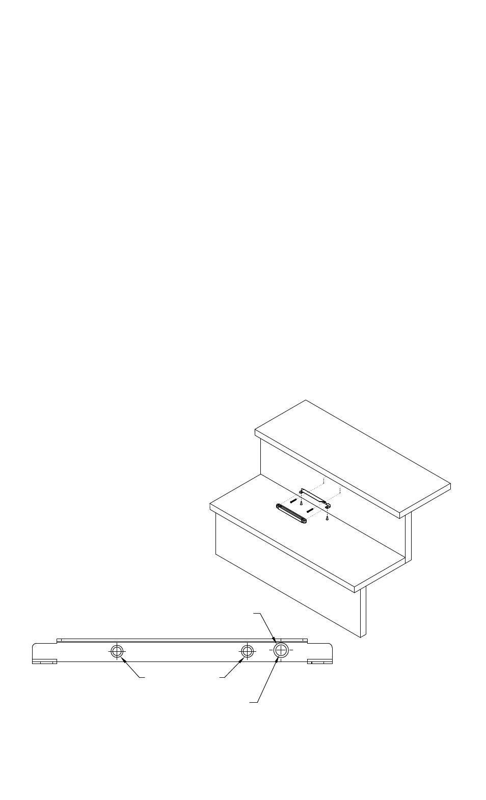
1) Determine the desired location for the fixture.
2) Install mounting accessory using #8 wood screws (included). Screw Anchors are provided if needed. If screws are difficult to
install, mark holes and drill 1/8” pilot holes. NOTE: DO NOT OVER TIGHTEN SCREWS.
3) Alternate mounting methods may require additional hardware not provided.
4) If desired, a wireway hole can be drilled through the riser. Locate the wireway hole on the mounting accessory. (SEE FIG. B)
Drill hole though riser. (suggested 1/4” [6.5 mm] hole)
5) Thread the fixture wire through the wireway hole.
6) Mount fixture to accessory using included #10 machine screws.
7) Refer to fixture instructions for wiring connections.
Kichler Design Pro LED
Accesorio de montaje del artefacto debajo del riel.
Instrucciones de instalación
P/N: 15717SS, 15718SS, 15719SS
Dev. No: CP300357SS, CP300358SS, CP300359SS
LEA CUIDADOSAMENTE TODAS LAS INSTRUCCIONES ANTES DE COMENZAR LA INSTALACIÓN.
GUARDE ESTAS INSTRUCCIONES.
INSTALACIÓN DEL ARTEFACTO 15717, 15718 ó 15719 (VEA LA FIG. A)
1) Determine el lugar deseado para el artefacto.
2) Instale el accesorio de montaje usando los tornillos para madera #8 (que se incluyen). Si se necesitan, se provee tornillos de
anclaje. Si tiene dificultad en instalar los tornillos, marque los agujeros y perfore agujeros piloto de 1/8”. NOTA: NO APRIETE
EXCESIVAMENTE LOS TORNILLOS.
3) Métodos de montaje alternativo pueden requerir herraje adicional que no se provee.
4) Si se desea, se puede perforar un agujero canal de alambres a través de la contrahuella. Localice el agujero canal de alambres
en el accesorio de montaje. (VEA LA FIG. B) Perfore el agujero a través de la contrahuella. (Se sugiere un agujero de 1/4” [6.5 mm]).
5) Pase el alambre del artefacto a través del agujero de canal de alambres.
6) Monte el artefacto al accesorio usando el tornillo para metales #10 que se incluye.
7) Consulte las instrucciones del artefacto para las conexiones de los alambres.
Date Issued: 8/23/13
IS-15717-BL
FIG. A
FIG. B
WIREWAY HOLE ON MOUNTING ACCESSORY
MOUNTING HOLES
1/4” WIREWAY HOLE DRILLED IN RISER
SEE REVERSE SIDE FOR CANADIAN FRENCH LANGUAGE
For warranty information please visit: http://www.landscapelighting.com/portal/warranty_page
Para informacion de ka garantia por favor visite: www.landscapelighting.com/portal/warranty_page