Rose Electronics Vista DVI Plus User Manual
Page 12
8
Installation and Operations Manual
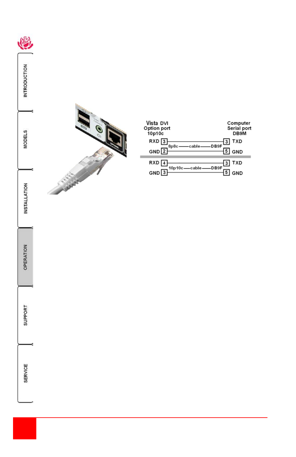
4- Serial command to the “Option” port
To switch channels using serial commands to the “Option” port, connect a serial
cable from a computer’s serial port to the “Option” port on the Vista DVI Plus unit.
The serial cable is usually an 8p8c connector on one end and a DB9F connector on
the other end. The “Option” port on the Vista DVI Plus uses a 10p10c socket. This
socket will accommodate a 10p10c and an 8p8c connector.
Serial cable pin-out
Set the serial port parameters to:
Baud rate – 1200
Data bits – 8
Stop bits – 1
Parity - None
Table 1. Serial Cable
With the proper serial cable connected from a computer and the Vista DVI Plus,
start your computer’s serial communication program (HyperTerminal, TeraTerm,
etc). Set the serial port parameters as designated in Table 1.
NOTE: The 1x4 unit uses an 8p8c to DB9 cable;
The 1x8 unit uses a straight through DB9 to DB9 cable.
To select a channel, enter the below code.
If entering ASCII characters from an attached computer’s keyboard,
use the numeric keys above the keyboard, not the keypad.
ASCII
Character Hex Decimal
Select channel 1:
1
0x31
49
Select channel 2:
2
0x32
50
Select channel 3:
3
0x33
51
Select channel 4:
4
0x34
52
- - - - - - - - - - - - - - - - - - - - - - - - - - - - - - - - - - -
Select channel 5:
5
0x35
53
Select channel 6
6
0x36
54
Select channel 7
7
0x37
55
Select channel 8
8
0x38
56