Installation, 4installation and operations manual – Rose Electronics Vista DVI Plus User Manual
Page 8
INSTALLATION
4
Installation and Operations Manual
Installation
Installation of the Vista DVI Plus unit consists of:
1.
Connecting the User console equipment to the unit
2.
Connecting the USB peripherals to the unit
3.
Connecting the Computers to the unit
4.
Applying power to all equipment
The following installation instructions are a guide to properly connecting all of the
equipment to the Vista DVI Plus unit. No special order is required but it is
recommended that power to the equipment and to the Vista DVI Plus unit be
applied after all connections have been made.
NOTE: The 1x4 and 1x8 models install and operate in the same manner.
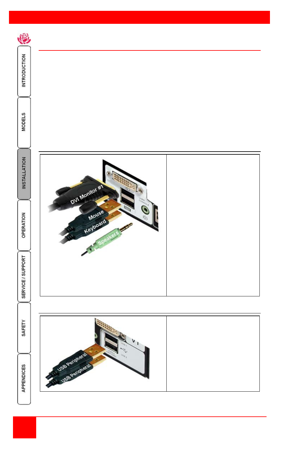
1- User Console Connections
User Console Connections
Connect a set of stereo
speakers to the audio input
jack if needed
Connect the USB keyboard
and USB mouse to the
corresponding USB ports
on the rear panel.
Connect a video monitor to
the DVI-I female connector
on the rear panel or VGA
connector (8 port model).
If you need to extend the
monitor past the 16’ max DVI
cable length, Rose Electronics’
CrystalView DVI products can
extend the distance up to 450’
over CATx cable or up to
33,000’ over fiber cabling.
2- Connecting the USB peripherals to the unit
USB Peripheral Connections
Connect up to 2 supported
USB peripherals to the USB
2.0 switched ports labeled
USB 1 and USB 2.
These USB ports provide
enumerated (transparent)
switching