Rose Electronics Vista DVI Plus User Manual
Page 9
Installation and Operations Manual
5
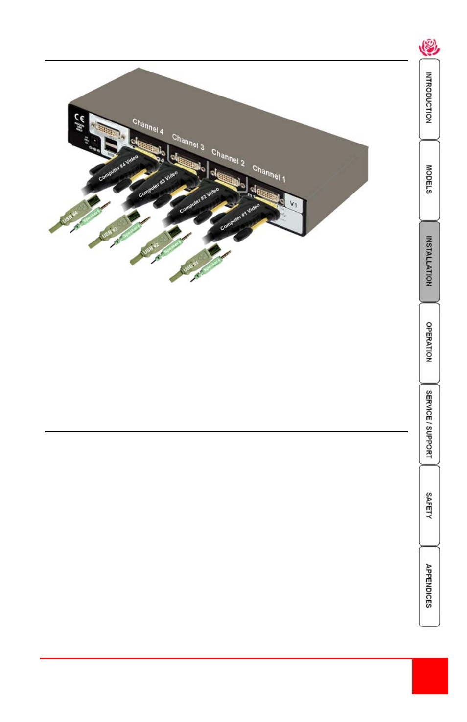
3- Connecting the Computers to the unit
Up to 4 single head computers can be connected to the Vista DVI Plus unit.
(8 single head computers on the 1 x 8 model)
Connect each computer’s DVI video output to the corresponding DVI-I connector on
the Vista DVI Plus rear panel using a DVI MM video cable.
Using a USB type A/B cable, connect each USB type B port on the Vista DVI Plus unit
to the corresponding USB type A connector on each computer.
A stereo 3.5mm audio cable is used to connect each computer’s audio output to the
audio input port on the Vista DVI Plus unit’s rear panel.
4- Applying power
Each unit is supplied with a 110-240 VAC 50/60Hz power adapter that supplies a +5
VDC, 4A, 20 watts to the Vista DVI Plus unit. There is no on/off power switch on the
unit. Operation begins as soon as power is supplied to the unit.
1- Connect the power adapter output connector to the +5V power jack on the
rear panel of the unit.
2- Connect the power cable to the IEC connector on the power adapter.
3- Connect the power cable to the main power supply source
Both the power adapter and the unit generate heat when in operation. Please provide
adequate air circulation to assure the ambient temperature does not exceed
104ºF (40º C).