Wiring, Features – Whelen 295HFSC9 User Manual
Page 3
Page 3
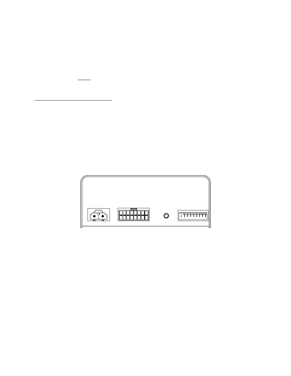
Main
Power
Connector
Harness
Connector
1
8 7 6 5 4 3 2
16 15 14 13 12 11 10
9
Dip
Switch
Bank
Radio
Volume
Adjustment
On
8
7
6
5
4
3
2
1
Wiring
Connecting to Power:
1.
Using appropriately sized wire, extend the RED and BLACK wires
from the Main Power Connector, through the firewall and into the
engine compartment (refer to the Wire Gage Calculation Chart
located on the last page of this manual to determine the proper wire
size for your application).
2.
Follow the factory wiring harness towards your vehicle’s battery.
WARNING! All customer supplied wires that connect to the positive
terminal of the battery must be sized to supply at least 125% of the
maximum operating current and FUSED at the battery to carry that
load. DO NOT USE CIRCUIT BREAKERS WITH THIS PRODUCT!
3.
Install a user supplied 20A fuse block on the end of the RED wire.
Connect the fuse block to the battery using no more than 2 feet of
wire. Do not install the fuse into the fuse holder yet!
4.
Connect the BLACK wire directly to the NEGATIVE battery terminal.
Connecting to your Speaker(s):
1.
Route the ORG, WHT/ORG, YEL and WHT/YEL wires (harness
connector positions 5, 6, 7 & 8) along the factory wiring harness
towards your speakers.
2.
Connect the ORG wire (pos 6) to the POSITIVE (+) terminal on
speaker #1. Connect the YEL wire (pos 8) to the POSITIVE (+)
terminal on speaker #2.
3.
Connect the WHT/ORG wire (pin 8 to the NEGATIVE (-) terminal on
speaker #1. Connect the WHT/YEL wire (Pin 7) to the NEGATIVE (-)
terminal on speaker #2.
Hands-Free Siren (optional):
Refer to the wiring diagram for all wiring information for this optional
connection.
Radio Rebroadcast (optional):
The two (2) BLU wires are used to connect your two-way radio’s external
speaker for radio rebroadcast. This is an optional connection and will not
effect the other operations.
Radio rebroadcast volume can be adjusted from the rear as shown below.
Note: Radio rebroadcast will NOT work with amplified remote
speakers! If your remote speaker is amplified (I.E.: contains a power
amp circuit in the speaker assembly), do not enable the radio re-
broadcast feature.
Backlight (optional):
Connecting the WHT wire to an ignition-controlled circuit enables
backlighting when the unit’s power switch is off.
Installation will be complete after a 20A fuse has been installed in the Main
Power Connector fuse block. Now inspect the fuses on the bottom of the
unit and at the battery. If any of these fuses are blown, carefully inspect all
of the circuit wires and make sure they are wired correctly. Replace the
blown fuses with ones of an identical amp rating. If these fuses blow after
installation or activation, contact Whelen Engineering Technical Support.
Features
Stereo/Mono Sound Control - The 295HFSC9
power switch has three
positions; Center (Off), Down (On/Mono) & Up (On/Dual). When this
switch is Off, the unit will not function. When the switch is in either On
position, the siren is functional and may be activated at the operator’s
discretion. In the On/Mono position, speakers #1 & #2 will produce
identical siren tones. In the On/Dual position, speakers #1 & #2 can be
configured to simultaneously produce completely different siren tones
(refer to the siren configuration tables for detailed configuration settings).
NOTE: If the unit is connected to the vehicle’s horn ring circuit, the vehicle
horn is disabled when the power switch is in the ON position.
Park-Kill Siren Shutdown - This feature allows the operator to disable an
active siren whenever the transmission is placed in Park. To enable this
feature, the WHT/BRN wire is connected to the output signal of the
transmission’s park/neutral safety switch. To restore normal siren
operation, turn the rotary knob to HF, MAN, STBY or RAD. The siren is
now reset for normal operation. IMPORTANT! This feature may effect
the vehicle warranty. Whelen Engineering recommends that the
vehicle manufacturer be contacted to learn what effect, if any, this
product will have on warranty considerations.
“Siren In Use” Output Signal - This feature provides an output signal that
is active whenever a repetitive cycling siren tone is active (ex. Wail, Yelp,
Piercer). This output signal is not enabled with Airhorn or manual tone
activation.
Hands-Free Operation - This feature offers the ability to activate siren
tones using the vehicle’s steering wheel horn ring. When the rotary knob is
in the HF position, the siren functions are placed in a standby mode. Siren
tones are activated by a single “tap” on the MAN button or on the vehicle’s
steering wheel horn button (if the vehicle’s horn has been wired to the
siren).
Independant Short Circuit Control - This feature implements non-
destructive, short circuit protection into the siren design. If one speaker
was to short, the other speaker will remain fully operational and
unaffected. When the short has been resolved, that speaker will
automatically return to normal operation.