Wiring diagram, Caution, Battery – Whelen 295HFSC9 User Manual
Page 4: Page 4
Page 4
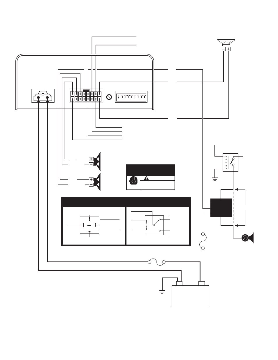
CAUTION
Loud siren noise can cause
hearing damage and/or loss.
Refer to OSHA Section 1910.95 prior
to putting ANY siren into service!
Wear
Protection!
ACTIVATION OF THIS
SIREN MAY DAMAGE
UNPROTECTED EARS!
VEHICLE
HORN
HORN
RELAY
TO
HORN
RING
WHT/VIO - No Connection
GRN*
GRY - “Siren in Use” output (switched to ground)
WHT - Backlight**
** onnect to an ignition
12-volt circuit
controlled,
c
(optional).
NOTE: The horn ring inputs
can also be wired to other types
of customer supplied control
switches such as a foot switch.
Use the WHT/GRN wire if Positive
Switching is desired or use the
GRN wire if Negative switching is
desired.
WHT/BRN (Park-Kill) - Positive Activation
WHT/GRN*
CUT
To
+12VDC
X
X
3 AMP
FUSE
20 AMP
FUSE
(-)
Battery
(+)
100 WATT
SPEAKER
100 WATT
SPEAKER
TWO-WAY
RADIO SPEAKER
(Non-Amplified)
* see “Horn Ring Transfer Relay
Table” for wiring information.
Horn Ring
Transfer Relay
(See table for
wiring info)
To Vehicle
Car Horn
From Vehicle
Horn Relay
To +12VDC
(Fuse @ 3A)
To +12VDC
(Fuse @ 3A)
VIO
VIO
WHT/GRN = for POS switching
GRN = for NEG switching
WHT/GRN = for POS switching
GRN = for NEG switching
30
87A
85
86
87
To Vehicle
Car Horn
N.O.
N.C.
From Vehicle
Horn Relay
Customer Supplied Horn Ring
Transfer Relay Table
Generic
Style
Bosch
Style
™
On
8
7
6
5
4
3
2
1
1
9
YEL
ORG
WHT/YEL
WHT/ORG
VIO
BLU
BLU
Wiring Diagram