Possible mounting positions, Mounting the speaker to bracket, Installation – Whelen SABKT1 User Manual
Page 2
Page 2
Possible Mounting Positions:
The SA314 or SA315 can mount to the universal bracket in a variety of positions depending on what your mounting
requirements are. The only necessity is that the speaker wires exit the bottom, (toward the ground) since this hole also serves as the drainage
hole for the speaker.
SA315 / Rear View
N e w
drain
hole
w i r e
exit &
drain
h o l e
w i r e
exit &
drain
h o l e
w i r e
exit &
drain
h o l e
N e w
drain
hole
Side View
1/4 - 20 X 1-1/2"
HEX HEAD SS
1/4" SPLIT
LOCK WASHER
1/4 X 20 X 1-1/4
HEX HEAD
SA315
SA314
#14 X 1" PPHSMS
1/4" INTERNAL TOOTH
LOCKWASHER
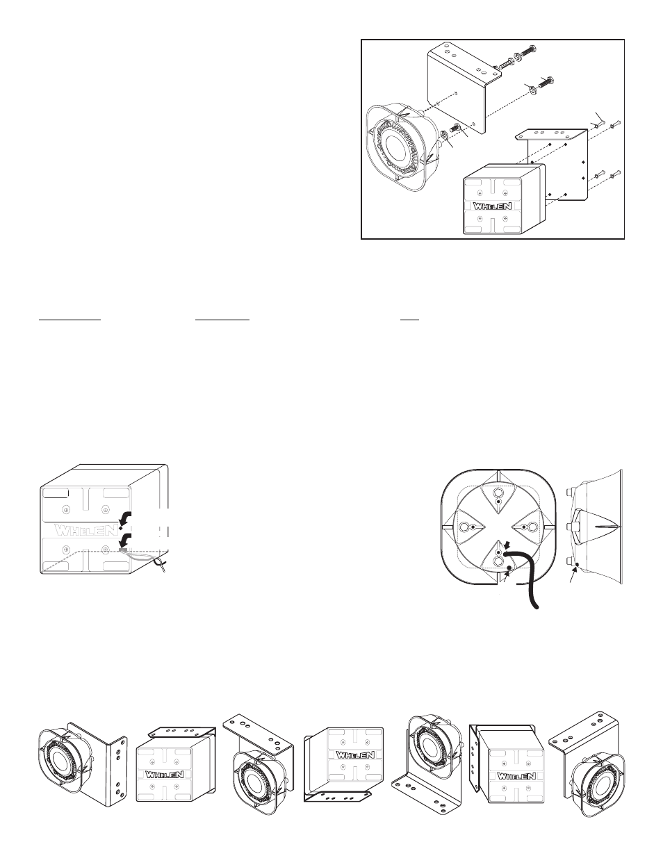
Mounting
the Speaker
to Bracket
1/4" SPLIT
LOCK WASHER
EXISTING
DRAIN HOLE
NEW DRAIN
HOLE HERE
SA314
Selecting a Mounting Location: The mounting location should not only be as
flat as possible but also allow the speaker to project its tone parallel with the road.
For specific applications for the universal bracket, refer to the following pages.
Installation:
1.
Position the bracket onto the desired mounting area and mark off the
mounting holes using the bracket as a template.
2.
In the center of the 4 holes you marked off, drill a 1/8 inch pilot hole into the
mounting surface for each of the mounting screws then enlarge the pilot
holes with a 9/32 inch drill. If you can get access to the other side of the
mounting area, and it is not too thick, you may want to substitute the
mounting screws with nuts, bolts and washers (customer supplied) of
comparable strength and thickness.
3.
Secure the bracket onto the mounting surface with the supplied mounting
hardware. NOTE: You may need a socket and drill to drive the screws.
4.
Attach speaker to bracket with the supplied mounting hardware then extend
the WHITE (Positive) and BLACK (Negative) speaker wires to your amplifier
and connect as shown in the amplifiers instructions.
WARNING: Speaker wires must exit the bottom of the speaker.
The wire hole also serves as a drainage hole. Improper mount-
ing will result in siren driver failure and void the siren warranty.
IMPORTANT NOTE: In most applications the existing drain hole
will work fine. However, since this mounting bracket can mount
in a variety of positions the drain hole in the bottom of the
speaker can be ineffective if the speaker is mounted with the
drain hole facing to the side. If your application does not allow
this an alternate drain hole may be drilled.
Drilling a drain hole / SA314:
Drill a small drainage hole in the
area indicated, using a 1/8” (.125) drill bit. There is a second wall
behind the outer surface that you must not drill through. Use a drill
stop set to a 1/4” depth. This will insure that you don’t hit any internal speaker parts while drilling the hole.
Drilling a drain hole / SA315:
Remove the bolts that hold the driver to the speaker body and slide
the driver out. Drill a small drainage hole in the rear of the speaker as shown. The hole should be drilled in the rear, on the curved part of the speaker body
(See side view) using a 1/8” drill bit. Make sure the hole is located on the bottom (depending on the position the speaker will be in after mounting). Be sure
you drill through both the outer and inner walls of the siren housing so the drain hole will reach the driver compartment. Reassemble the speaker, reinstalling
the driver into the speaker body and securing the driver with the bolts you removed. WARNING: When you are reassembling the speaker, be very
careful not to pinch the wires between the siren driver and the housing. Feed the wires through the wire hole first.
APPLICATION
HARDWARE
QTY
2004-05 DURANGO . . . . . . . . . . . . . . . . . . . . NUT: 5/16-18 Hex SS 1/2" Diameter. . . . . . . . . . . . . . . . . . . . . . . .2
2004-05 DURANGO . . . . . . . . . . . . . . . . . . . BOLT: 5/16-18 X 1 Hex Head SS . . . . . . . . . . . . . . . . . . . . . . . . . .2
2004-05 DURANGO . . . . . . . . . . . . . . . . . . . . WASHER: 5/16 Split Lock. . . . . . . . . . . . . . . . . . . . . . . . . . . . . . . .2
2001 TAURUS . . . . . . . . . . . . . . . . . . . . . . . . SCREW: 1/4 X 1" Hex Washer Head Self Drilling . . . . . . . . . . . . .4
For Any Application / Bracket to vehicle . . SCREW: 5/16 X 1" Hex Head SMS SS . . . . . . . . . . . . . . . . . . . . .4
For Any Application / Bracket to vehicle . . WASHER: 5/16" Flat SS 3/4" Outer Diameter . . . . . . . . . . . . . . . .2
Mounting SA314 Speaker To Bracket . . . . . SCREW: 14 X 1 PPHSMS A Point . . . . . . . . . . . . . . . . . . . . . . . . .4
Mounting SA314 Speaker To Bracket . . . . . WASHER: 1/4 Internal Tooth Lock . . . . . . . . . . . . . . . . . . . . . . . . .4
Mounting SA315 Speaker to Bracket . . . . . SCREW: 1/4-20 X 1-1/2 Hex Head SS . . . . . . . . . . . . . . . . . . . . . .3
Mounting SA315 Siren Driver to Housing. . BOLT: 1/4 X 20 X 1-1/4 Hex Head . . . . . . . . . . . . . . . . . . . . . . . . .1
Mounting SA315 Speaker to Bracket . . . . . WASHER: 1/4 Split Lock Washer . . . . . . . . . . . . . . . . . . . . . . . . . .4
IMPORTANT: It is the responsibility of the installation technician
to make sure that the installation and operation of this product
will not interfere with or compromise the operation or efficiency
of any vehicle equipment!
The SA315 siren speaker mounting kit comes with
3 long bolts (1/4-20 X 1-1/2” Hex Head SS). The
longer bolts are necessary to go through the
mounting bracket, through the siren housing and
into the siren driver. They will replace 3 of the 4
shorter bolts (“A”) that now secure the siren driver
to the speaker housing. Your speaker is shipped
with 2 or more of the shorter bolts installed. A short
bolt must be used in the hole that does not go
through the bracket so it will properly secure the
driver to the housing. If you need to remove all 4
bolts at once be sure to hold the driver in place.