Adjustable mounting foot, Standard mounting foot, Permanent mounting – Whelen DI2S800 User Manual
Page 2: Strap mounting, Slide bolt mounting (permanent)
Page 2
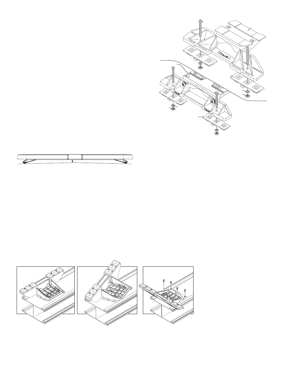
Mounting
Pad
Adjustable
Mounting
Foot
Washer
Nut
Mounting
Plate
Standard
Mounting
Foot
Mounting
Pad
Washer
Nut
Mounting
Plate
Bolt
Bolt
IMPORTANT! The lightbar should be located a minimum of 16" from any
radio antennas!
Permanent Mounting:
1.
Locate the mounting foot and locking plate included with your lightbar. If not already
present, install the locking plate onto the mounting foot using the supplied set screws.
This plate should be centered from side to side on the mounting foot.
2.
Flip lightbar upside-down to expose bottom of extrusion and place mounting foot onto extrusion.
3.
Rotate the mounting foot 90° in a counter-clockwise direction. Make sure that the edges of the foot
swing into position under the extrusion mounting lip.
4.
Repeat procedure for remaining foot and return lightbar to its right side-up position.
5.
Position the lightbar onto the vehicle roof in the desired mounting location. One often
selected location is directly above the B-pillars. This area is the strongest part of the
roof. Refer to your lightbar manual for your lightbars cable exit location, to be sure
that the lightbar is facing the proper direction.
6.
Adjust the two mounting feet outwards as close to the edge of the roof as possible.
Make sure that both mounting feet are in full contact with the roof (See below). There
should be no less than 1/2” clearance between the roof and the lightbar at their
closest point. When the mounting feet are in the proper position, lightly tighten the
allen head set screws.
7.
Turn the lightbar upside down and firmly tighten all of the set screws from step 6
(2 or 4 per side).
8.
Note that on the adjustable foot, use the hole in the pad as a guide to drill the two holes into
the mounting foot at the locations shown.
9.
Place the lightbar in its final mounting position on the vehicle and mark the mounting hole locations off onto the
mounting surface. Remove lightbar and drill the mounting holes.
10. Place the lightbar back onto the vehicle lined up with the mounting holes and secure the mounting feet to the vehicle
using the supplied hardware.
NOTE: Unless otherwise specified, the lightbar mounting feet must be sitting as close to the edge of the roof as possible. They must also be
in full contact with the roof and not be hanging off the edge.
IMPORTANT: For strap mounting, be sure you have the right sized
lightbar for your vehicle. The bar should be approximately the same
width as the vehicle roof. If too large or small it will not mount properly
and may come loose during driving.
1/2" MIN. CLEARANCE
Strap Mounting:
1.
Locate the mounting foot, mounting plate and tinnerman plate included with
your lightbar. If not already present, install the mounting plate onto the
mounting foot. When properly positioned, this plate is centered from side-to-
side on the mounting foot.
2.
Flip the lightbar upside-down to expose the bottom of the extrusion and place
the mounting foot onto the extrusion.
3.
Rotate the mounting foot 90° in a counter-clockwise direction. Make sure that
the edges of the mounting foot swing into position under the extrusion
mounting lip. Install a tinnerman plate onto the extrusion in the same manner.
Slide Bolt Mounting (Permanent):
1.
Position the slide bolt mounting plates onto the bottom of the lightbar extrusion. These plates rotate into position the same way as the mounting foot. Position the plates as
far outward as possible (if a 3rd mounting plate is used, it should be positioned under the center of the lightbar).
2.
Secure the plates to the extrusion using the set screws provided.
3.
Position the lightbar onto the vehicle and mark the mounting bolt locations. Drill the necessary mounting holes using an appropriately sized drill bit sized for a 1/2” bolt.
4.
Repeat this procedure for the remaining mounting foot and tinnerman plate and
return the lightbar to its right side-up position.
5.
Position the lightbar onto the vehicle roof in the desired mounting location. One
often selected location is directly above the B-pillars. This area is the strongest
part of the roof. Refer to your lightbar manual for cable exit location, to be sure
that the lightbar is facing the proper direction.
6.
Adjust the two mounting feet outwards so that they are as close to the edge of
the roof as possible. Both mounting feet must be in full contact with the roof. Be
sure that there is no less than 1/2” clearance between the roof and the lightbar
at their closest point. When the mounting feet are in their proper position, lightly
tighten the mounting foot allen head set
screws.
7.
Return the lightbar to an upside-down
position. Slide each tinnerman plate
outwards until it is fully engaged with its
corresponding mounting foot. With the
mounting feet and tinnerman plates in their
proper positions firmly tighten all of the set
screws (2 or 4 per side). Flip the lightbar
right side-up and return it to its mounting
position.