Routing the cables, Control cable, Scan-lock™ (white-violet) – Whelen DI2S800 User Manual
Page 4
Page 4
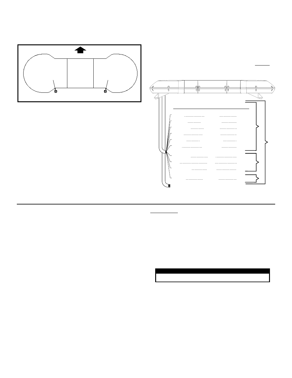
FRONT
For lightbars with
cables exiting the
Driver side of the
extrusion
Drill cable access hole in an area
appropriate for your lightbar
(see Warning).
For lightbars with
cables exiting the
Passenger side of
the extrusion
Routing the Cables:
1.
To protect the headliner from damage caused by drilling the cable
access hole through the vehicle roof, lower the headliner before
drilling to allow a 5” to 7” distance between roof and headliner.
WARNING!
There is a roof support member that spans the
distance between the driver’s and passenger’s side. DO NOT
DRILL THROUGH THIS MEMBER! Adjust the location until
the hole can be drilled without contacting this support
member. Refer to “Safety First” on Page 1 for important
precautionary information.
2.
Using a 1” hole saw, drill the cable access hole.
3.
Use a round file to de-burr the edges of the cable access hole and
insert a 1” grommet (customer supplied) into the hole.
4.
Insert the cables through the cable access hole into the vehicle. Use
RTV silicone to weatherproof the access hole after the cables are
pulled completely into the vehicle.
5.
Route the cables one at a time to your power source. It is left to the
installation technician’s discretion where to run the cables, as
vehicles will vary.
Control Cable:
Route the cable towards a high-current switch panel such as the Whelen
model PCC10. Note: The use of switches with an insufficient current
rating will cause switch failure! Switches with a current rating of less
than 20 amps should not be used. For proper operation The ground
cable (BLACK) must be connected to the vehicle’s chassis ground.
WARNING! All customer supplied wires that connect to the
positive terminal of the battery must be sized to supply at
least 125% of the maximum operating current and FUSED at
the battery to carry that load. DO NOT USE CIRCUIT
BREAKERS WITH THIS PRODUCT!
Scan-Lock™ (white-violet)
With the desired lighthead activated:
TO CHANGE PATTERNS: To cycle forward to the next available pattern
apply +12 volts to the WHITE-VIOLET wire for less than 1 second and
release. To cycle back to the previous pattern apply +12 volts to the
WHITE-VIOLET wire for more than 1 second and release.
TO CHANGE THE DEFAULT PATTERN: When the desired pattern is
displayed, allow it to run for more than 5 seconds. The lighthead will now
display this pattern when initially activated.
TO RESTORE THE FACTORY DEFAULT PATTERN: Turn power to the
lighthead off. While applying +12 volts to the WHITE-VIOLET wire, turn
power to the lighthead on. The factory default pattern is now displayed.
Use a Normally Open Momentary Switch for Scan-Lock™ operation.
Route
cable
to
customer
supplied
switch
box.
Oscillators
Front Flashers
Rear Flashers
Take-Down
GREEN
RED/WHITE
GRN/WHT
RED
RED/BLACK
WHT/VIO
WHITE/BLK
WHITE
YELLOW
BLUE
Inner
Outer
Center
Scan-Lock™
Drivers Alley
Passenger Alley
15 Amps
15 Amps
7.5 Amps
15 Amps
15 Amps
3 Amps
7.5 Amps
7.5 Amps
7.5 Amps
7.5 Amps
Color
Fuse @
Lower
Level
Upper
Level
Misc.
NOTE: If dual, lower level MR-11 lightheads are used, their control
lines must be fused at 15 Amps.
To Chassis Ground
Function
Control Cable
CONTROL CABLE: A control cable with all available options for the
DELTA™ is shown for reference. Not all options are available in all
lightbars. For the wire I.D. of your lightbar, refer to the list included
with the lightbar. You will have either a 10 or 17 conductor cable.
VIOLET . . . . . . . . . . . . Optional Flashers . . . . . . . . . . .Fuse @ 7.5 amps
WHITE/YELLOW. . . . . Optional Flashers . . . . . . . . . . .Fuse @ 7.5 amps
BLACK/WHITE . . . . . . Optional Flashers . . . . . . . . . . .Fuse @ 7.5 amps
BLUE/ORANGE . . . . . Optional Flashers . . . . . . . . . . .Fuse @ 7.5 amps
BLUE/BLACK . . . . . . . Optional Flashers . . . . . . . . . . .Fuse @ 7.5 amps
BLUE/WHITE . . . . . . . Optional Flashers . . . . . . . . . . .Fuse @ 7.5 amps
GREEN/BLACK . . . . . Optional Flashers . . . . . . . . . . .Fuse @ 7.5 amps
WHITE/VIOLET . . . . . . Scan-Lock™ . . . . . . . . . . . . . . . . . Fuse @ 1 amp
WHITE/BLACK . . . . . . Take-Downs . . . . . . . . . . . . . . . Fuse @ 7.5 amps
GREEN/WHITE . . . . . . Optional Flashers . . . . . . . . . . . Fuse @ 7.5 amps
WHITE . . . . . . . . . . . . . Drivers Side Alley . . . . . . . . . . . Fuse @ 7.5 amps
YELLOW . . . . . . . . . . . Passengers Side Alley. . . . . . . . Fuse @ 7.5 amps
BLUE. . . . . . . . . . . . . . Optional Flashers . . . . . . . . . . . Fuse @ 7.5 amps
RED . . . . . . . . . . . . . . . Inner Rotators . . . . . . . . . . . . . . Fuse @ 15 amps
RED/WHITE . . . . . . . . Outer Rotators . . . . . . . . . . . . . . Fuse @ 15 amps
RED/BLACK . . . . . . . . Center Rotators . . . . . . . . . . . . . Fuse @ 15 amps
GREEN . . . . . . . . . . . . Oscillating Rotators . . . . . . . . . . Fuse @ 15 amps
NOTE: For 400 Series LED flashers, LR11 Alley lights or LR11 take-
downs, use a 3 amp fuse.
Flash Patterns:
1. SignalAlert™ 1 Alternates with 2
2. SignalAlert™ 1 & 2 Simultaneous
3. SignalAlert™ 3 Cycles of 1A & 3
Cycles of 1B
4. CometFlash® 1 Alternates with 2
5. CometFlash® 1 & 2 Simultaneous
6. CometFlash® 3 Cycles of 2A & 3
Cycles of 2B
7. DoubleFlash 1 Alternates with 2
8. DoubleFlash 1 & 2 Simultaneous
9. DoubleFlash 3 Cycles of 3A and 3
Cycles of 3B
10. SingleFlash 1 Alternates with 2
11. SingleFlash 1 & 2 Simultaneous
12. SingleFlash 3 Cycles of 4A and 4
Cycles of 4B
13. SteadyFlash 1 & 2 Steady / 3 & 4
Single Flash
14. Steady 1, 2, 3 & 4 Steady
CAUTION! DO NOT LOOK DIRECTLY AT THESE LED’S WHILE THEY ARE ON.
MOMENTARY BLINDNESS AND/OR EYE DAMAGE COULD RESULT!
I M P O R TA N T W A R N I N G !
IMPORTANT! Before returning this vehicle to active service, visually confirm the proper operation of this product, as well as all vehicle
components/equipment.