Whelen DI2S800 User Manual
Page 8
Page 8
B
A
S
E
EXTRUSION
B
A
S
E
EXTRUSION
Upper
Lower
8 X 3/8"
PPHSMS
410 SS
8 X 3/8"
PPHSMS
410 SS
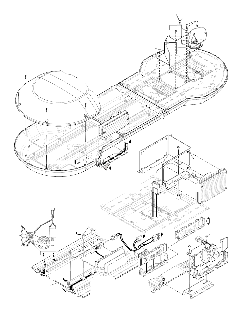
Servicing your Lightbar:
R
To
power
distribution
board
Connect
to
other
MR1
1
Remove protective
backing from tape
before mounting
Secure bracket to
extrusion using
supplied sheet
metal screws
Insert grommets
into extrusion
500
Series
Lighthead
500
Series
Lighthead
500
Series
Lighthead
Dome
400
Series
Lighthead
400
Series
Lighthead
400
Series
Lighthead
MR1
1 TIR3
Flasher
Dome
6 X 3/4"
PPHSMS
410 / SS
8-32 X 3/4
P P H M S
BASE
EXTRUSION
F R O N T
BRACKET
R E A R
BRACKET
INSIDE
COVER
NOTE: If you need to remove
the oscillator from the lightbar
you must re-mount it in the
exact same position.
Hook bracket
over extrusion.
Hook bracket
over extrusion.
Secure bracket to
fastex grommets
installed into
base.
Secure bracket to
fastex grommets
installed into
base.
Secure bracket to
fastex grommet
installed into
base.
This section covers the removal and installation
of the components of your lightbar for repair or
replacement purposes. All options plug into the
distribution module which is mounted on the
base extrusion on the lower level. The sockets
on the distribution module are labeled for easy
F a s t e x
grommet
Mounting
bracket
Connector plugs
into distribution
module on lower
level.
D
o
m
e
:
Removal:
Installation:
The domes are held on by 8-32x1/2" phillips pan head metal screws
Remove the dome mounting screws and Pull dome(s) off.
Place dome on lightbar base making sure it sits properly.
Secure dome(s) with supplied 8-32 X 1/2 Inch metal screws.
RUBBER
BUMPER
Hook bracket
over extrusion
here.
5 0 0
S e r i e s :
.
1.
2.
3.
NOTE: A
is
MR11,
Slide lighthead into retainer and remove backing from double sided tape on bottom.
Insert tabs on back of retainer into slots in lightbar base ress down
Reinstall upper cover. The 3 tabs on top of the lighthead will fit into 3 slots in the cover.
.
500 Series LED
shown.
500 Series 5MM, 500 Series HALOGEN
500 SERIES TIR, LR11's and Flashers mount the same.
P
so tape will stick.
The oscillator mounts
directly to two fastex
grommets inserted into
the extrusion.
The oscillator
does not use a
mounting bracket.
Oscillator:
500 Series:
Lighthead
slides
into
slots
in r
etainer
Insert retainers tabs
into slots in the base
Insert retainers tabs
into slots in the base
Insert retainers tabs
into slots in the base
400 Series:
Install 4 grommets into
the mounting bracket &
1 into the
cover
the lightbar.
Secure lighthead to
mounting bracket using
Secure bracket (with
lighthead) to base cover
using supplied sheet
metal screws
1.
1.
1.
2.
2.
3.
3.
3.
inside
of
lighthead lens screws.
and plug
1.
2.
3.
Install 4 grommets into
the mounting bracket &
1 into the
cover
the lightbar.
inside
of
Secure lighthead to
mounting bracket using
lighthead lens screws.
Secure bracket (with
lighthead) to base cover
using supplied sheet
metal screws.
.
400 Series:
Same as
500 Series
Flasher:
INSIDE
COVER
BOSSES
GROMMET
GROMMET
Oscillator
(Top View)
Oscillator
(Top View)
Oscillator
(Top View)
Flasher
1.
1.
2.
2.
2.
3.
Install the 2 grommets into the lightbar inside
cover to which the rotator will mount.
Secure the front of the rotator by slipping its base
over the 2 bosses protruding from the inside
ecure the rear to the grommets you
using the 2 supplied sheet metal screws.
The rotator plugs into the distribution board
on the lower level.
cover. S
installed
Rotator:
1.
2.
3.
Install the 2 grommets into the lightbar inside
cover to which the rotator will mount.
Secure the front of the rotator by slipping its base
over the 2 bosses protruding from the inside
cover. Secure the rear to the grommets you
installed using the 2 supplied sheet metal screws.
The rotator plugs into the distribution board
on the lower level.
Dome:
identification.
RUBBER
BUMPER
B
A
S
E
EXTRUSION
LR1
1
Slide
bracket
into
extrusion.
2 screws
to secure.
LR11
Alley:
1.
1.
TIR3:
1.
2.
3.
4.
Secure lighthead to front bracket
lighthead lens screws.
Insert 2 fastex grommets into extrusion.
Place lighthead/bracket onto extrusion.
Slip rear bracket over extrusion and
with 2 sheet metal screws.
using
secure
MR11 /
4.