Amprobe AT-5000 Underground-Wire-Tracer User Manual
Page 10
8
The equipment and all accessories must be connected according to applicable standards VDE, EN or DIN as well as country-
specific regulations.
UNPACkING ANd INSPECTIoN
Your shipping carton should include:
1 x R-5000 Receiver
1 x T-5000 Transmitter
1 x CK-5000 Test leads and Ground Stake
1 x Instruction Manual
1 x Carrying case Nylon Bag
T-5000 TRANSMITTER SySTEM oVERVIEW
Controls
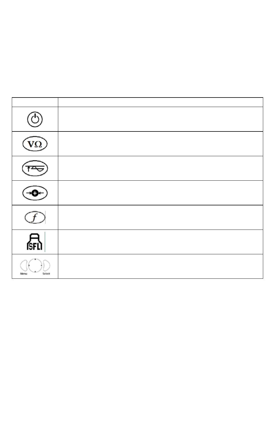
Control
description
Power oN – Push to turn the transmitter ON or OFF. An amber LED illuminates when the transmitter
is ON.
Circuit Condition – Available only in direct connection mode. Push to toggle through and view the
actual condition of the circuit in volts, milliamps, watts, and ohms.
output Level – Push to change the output level. Push repeatedly or use the left/right navigational
button to increases or decrease the output level.
Signal Select – Push to turn Signal Select ON or OFF for positive line identification.
frequency Select – Push to toggle through the active frequencies.
Sheath fault Locate (SfL) – Push to turn the SFL feature ON or OFF. A red LED illuminates when the
feature is ON.
4-Way Navigation Control – Push to select and navigate through the operational menu screens
and active frequency menu.