Amprobe AT-5000 Underground-Wire-Tracer User Manual
Page 34
32
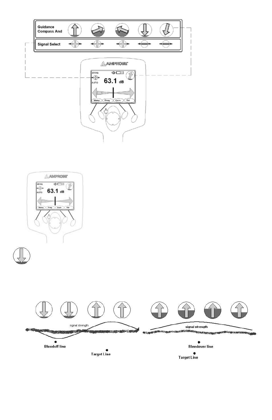
The presence of bleed over signals is indicated by the RED color filling the inside of the guidance compass indicator.
•
CENTER LINE PoSITIoN
The Left/Right display is tremendously useful in refining the precise location of the target line. The vertical black bar represents
the underground utility cable. Follow the vertical bar to determine the position of the cable. When shown at centerline it
indicates that the R-5000 Receiver is on top of the target.
Signal Select
The direction of the signal in the targeted line is determined by analyzing the sign of the demodulated Signal Select signal.
When the R-5000 receiver is positioned over a signal that carries an inverted field (i.e., one in which the phase is –180° from the
expected, the Guidance Compass points down, as shown below for a line that is bonded to the target line and carries return
current.
oPERATIoN
Decide which mode of operation to use for your application
1.
Induction
: Transmitter’s signal is emitted through the integrated antenna and is thereby inductively coupled with any
metallic lines located within a certain radius.
Base Frequencies (Hz): 9.82k, 82k
a.