3 installation – PLANET ICA-8200 User Manual
Page 6
6
Terminal block for I/O connectors:
Pin
Function
Description
1
GND
Digital Input: Only one set is designed in this camera
model. The internal device is also a photo-coupled electrical
relay, and the external device can be simply an On/Off
switch. Each set of On/Off switch can be connected as one
trigger source.
Digital Output: Each digital output pin to COM is a photo-
coupled relay on Normal Open status. External device can
directly connect to the terminals. However, the current that
will go through the 2 nodes must not exceed 130mA. An
external “Relay” can also be connected to the terminals as
an implementation. In this case, current (or/and voltage)
limitation is specified by the external Relay.
2
DI
3
GND
4
DO_COM
5
DO_NO2
6
DO_COM
7
DO_NO1
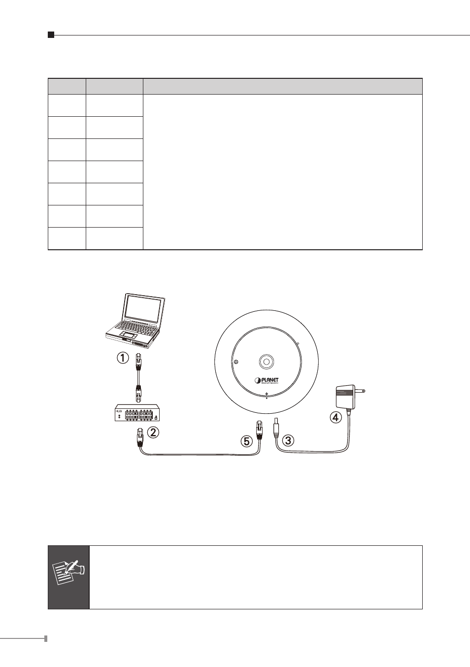
2.3 Installation
Step 1. Prepare a PC with Ethernet link to the network
Step 2. Connect an Ethernet cable
Connect LAN port (RJ-45) of the IP camera to a network switch. For
ICA-8200/ICA-8500, when this switch is a PoE device, you can ignore
the next step.
Note
For ICA-8000 series, if there has an IEEE 802.3af PoE switch in your
network, you can connect the IP camera’s LAN cable to this PoE
switch to obtain power. The power adapter is unnecessary when the IP
camera is powered by PoE switch.