Ipoe-162 installation – PLANET IPOE-162 User Manual
Page 17
17
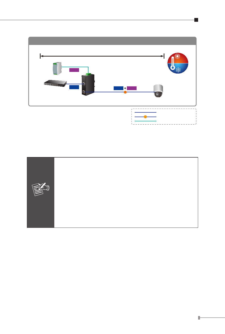
Power Line
1000Base-T UTP
PoE
1000Base-T UTP with PoE
IPOE-162
Industrial
Switch
Power
Supply
AC 24V/DC 24~48V
IPOE-162 Installation
-40 ℃
75 ℃
Power
Data
PoE
PTZ Camera
PoE
Power
Data
100 meters
Once IPOE-162 detects the existence of an IEEE 802.3at device, the
POE In-use LED indicator will be steady on to show it is providing
power.
Note
1. Due to the IPOE-162 PoE port supports 56V DC PoE
power output, please check and assure the Powered
Device (PD) acceptable DC power range is from 52
to 56V DC. Otherwise, it will damage the Powered
Device (PD).
2. If the connected device (PD) is not fully complying
with IEEE 802.3at Power over Ethernet or in-line
power device, the IPOE-162 might encounter incom-
patible issue which fails to power up the devices.
IPOE-162 and IPOE-162S, the IEEE 802.3at Injector Splitter
Installation
1. Connect the Power (Range from AC 24V or DC 24 ~ 48V) to 6-pin
terminal block of IPOE-162. The power LED will be steady on.
2. Connect a standard network cable from “Ethernet+DC” port of
IPOE-162 to “PoE In” port of IPOE-162S. The POE In-use LED of
IPOE-162 / IPOE-162S will light on continuance.