The system info tab, Power monitor, Board information – Altera 100G Development Kit, Stratix V GX Edition User Manual
Page 21: The system info tab –3, Power monitor –3 board information –3
Chapter 6: Board Test System
6–3
Using the Board Test System
August 2012
Altera Corporation
100G Development Kit, Stratix V GX Edition
User Guide
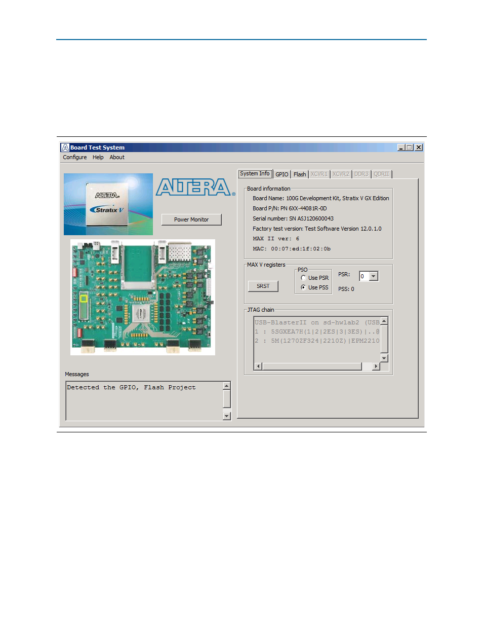
The System Info Tab
The System Info tab shows board’s current configuration. This tab displays the
contents of the MAX II registers, the JTAG chain, the board’s MAC address, the flash
memory map, and other details stored on the board.
shows the initial GUI for a board that is in the factory configuration.
The following sections describe the controls on the System Info tab.
Power Monitor
This button starts the Power Monitor application that measures and reports current
power and temperature information for the board. Because the application
communicates over the JTAG bus to the MAX II device, you can measure the power of
any design in the FPGA, including your own designs. For details, refer to
Board Information
The Board information controls display static information about your board.
Figure 6–2. Board Test System Graphical User Interface