General information, General information –14 – Altera 100G Development Kit, Stratix V GX Edition User Manual
Page 32
6–14
Chapter 6: Board Test System
The Power Monitor
100G Development Kit, Stratix V GX Edition
August 2012
Altera Corporation
User Guide
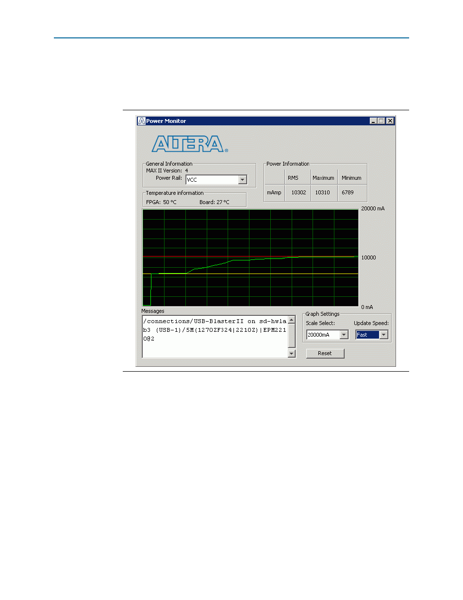
The Power Monitor communicates with the MAX II device on the board through the
JTAG bus. A power monitor circuit attached to the MAX II device allows you to
measure the power that the Stratix V GX FPGA device is consuming.
shows the Power Monitor.
The following sections describe the Power Monitor controls.
General Information
The General information controls display the following information about the
MAX II device:
■
MAX II version
—Indicates the version of MAX II code currently running on the
board. The MAX V code resides in the <install
dir>\kits\stratixVGX_5sgxea7nf45_100g\factory_recovery and <install
dir>\kits\stratixVGX_5sgxea7nf45_100g\examples\max2 directories. Newer
revisions of this code might be available on the
Altera website.
■
Power Rail
—Indicates the currently-selected power rail.
f
For more information on the power rails, refer to th
Figure 6–7. The Power Monitor