Figure 3–1, Figure 3–1. switch locations and default settings, Arria v soc – Altera Arria V SoC User Manual
Page 12
Advertising
3–2
Chapter 3: Board Setup and Defaults
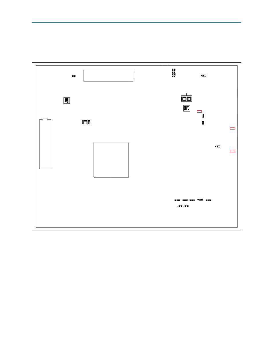
Factory Default Switch and Jumper Settings
Arria V SoC Development Kit
June 2014
Altera Corporation
User Guide
1
The SD card, Max V system controller, and CFI flash are already programmed with
the factory default files. For more information, refer to
.
Figure 3–1. Switch Locations and Default Settings
Arria V SoC
J37
1
0
1
0
1
0
1
0
J38
J39
J40
J41
CSEL0
J45
SEL1
J46
SEL0
CLK OSC2
CSEL1
BSEL0
BSEL1
BSEL2
1
0
J6
1.2V
FMC VAR
1.5V
1.8V
2.5V
HPS FPGA FMC MAX
SW4
1 2 3 4
ON
SW1
3 2 1 0 3 2 1 0
HPS
J18
J23
J30
Not a jumper
Not a jumper
Not a jumper
Not a jumper
FPGA
ON
1 2 3 4 5 6 7 8
J3
FMCB_JTAG_EN
SW2
1 2 3 4
SECURITY
FACT LOAD
Si570
CLK125A
ON
SW3
FMCB
FMCA
0 1 2 3 4
MSEL
ON
1 2 3 4 5 6
J7
LMK_OSC_SEL
J28
JTAG_MIC_SEL
J19
JTAG
HPS SEL
J21
JTAG
SEL
Advertising