Altera PowerPlay Early Power Estimator User Manual
Page 17
Chapter 3: Using Cyclone III PowerPlay Early Power Estimator
3–5
PowerPlay Early Power Estimator Inputs
© June 2009 Altera Corporation
PowerPlay Early Power Estimator User Guide for Cyclone III FPGAs
Figure 3–2
and
Figure 3–3
show examples of a TFF and a 4-bit counter.
Toggle %
Enter the average percentage of logic toggling on each clock cycle. The toggle percentage ranges
from 0 to 100%. Typically, the toggle percentage is 12.5%, which is the toggle percentage of a
16-bit counter. To ensure you do not underestimate the toggle percentage, you can use a higher
toggle percentage. Most logic only toggles infrequently, and hence toggle rates of less than 50%
are more realistic.
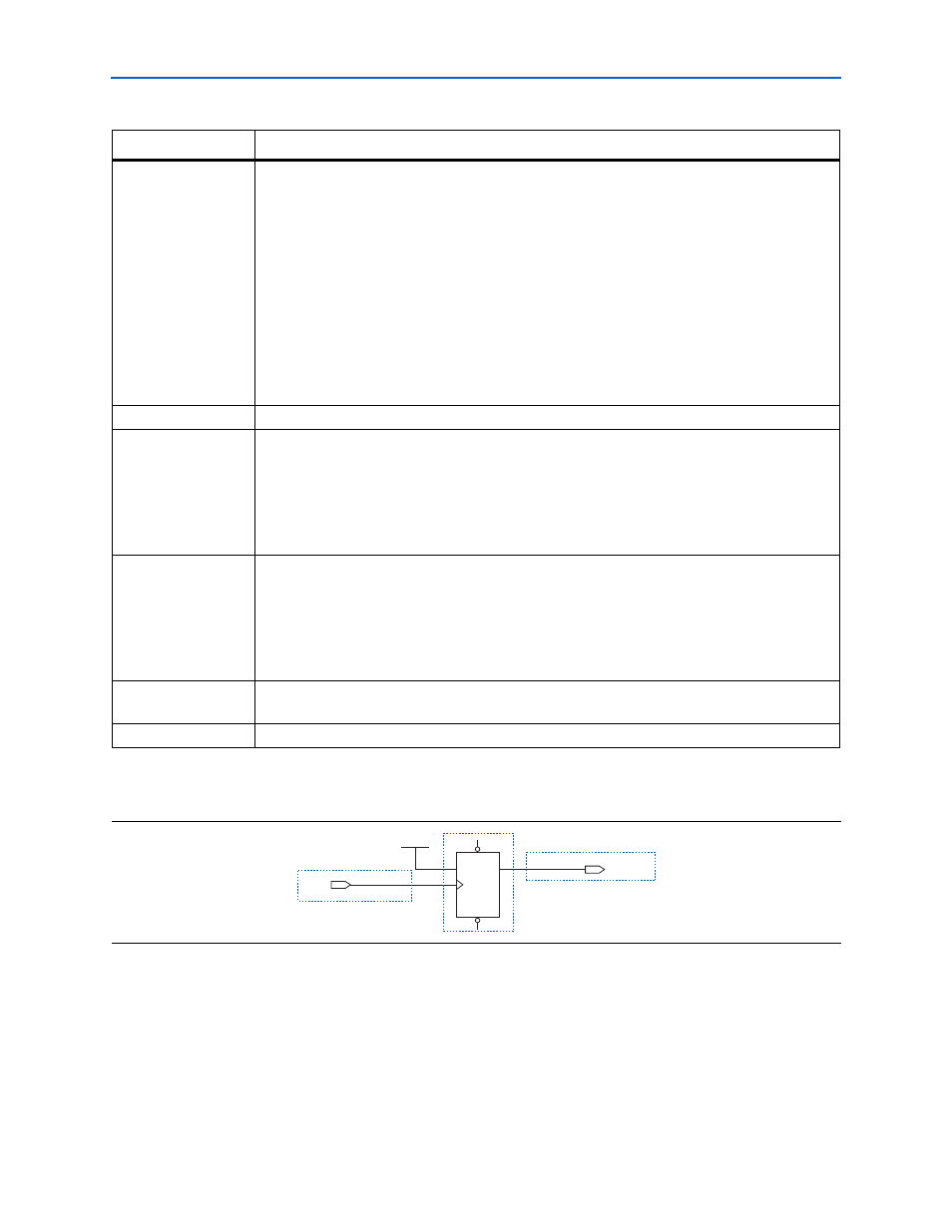
For example, a T-flip-flop (TFF) with its input tied to V
CC
has a toggle rate of 100% because its
output is changing logic states on every clock cycle (
Figure 3–2
).
Figure 3–3
shows an example of
a 4-bit counter. The first TFF with the LSB output cout0 has a toggle rate of 100% because the
signal toggles on every clock cycle. The toggle rate for the second TFF with output cout1 is 50%
since the signal only toggles on every two clock cycles. Consequently, the toggle rate for the third
TFF with output cout2 and fourth TFF with output cout3 are 25% and 12.5%, respectively.
Therefore, the average toggle percentage for this 4-bit counter is (100 + 50 + 25 + 12.5) /4 =
46.875%.
Average Fanout
Enter the average number of blocks fed by the outputs of LUTs and FFs.
Thermal Power (W),
Routing
This parameter shows the power dissipation due to estimated routing (in W).
Routing power is highly dependent on placement and routing, which is itself a function of design
complexity. The values shown are representative of routing power based on experimentation
across over 100 customer designs.
Use the Quartus II PowerPlay Power Analyzer for detailed analysis based on the routing used in
your design.
Thermal Power (W),
Block
This parameter shows the power dissipation due to internal toggling of the logic elements (in W).
Logic block power is a result of the function implemented and relative toggle rates of the various
inputs. The PowerPlay Early Power Estimator uses an estimate based on observed behavior across
over 100 customer designs.
Use the Quartus II PowerPlay Power Analyzer for accurate analysis based on the exact synthesis of
your design.
Thermal Power (W),
Total
This shows the total power dissipation (W). The total power dissipation is the sum of the routing
and block power.
User Comments
Enter any comments. This is an optional entry.
Table 3–2. Logic Section Information (Part 2 of 2)
Parameter
Description
Figure 3–2. TFF Example
PRN
CLRN
T
Q
TFF
clock
V
CC
INPUT
V
CC
OUTPUT
tff output