General i/o pins, General i/o pins –11 – Altera PowerPlay Early Power Estimator User Manual
Page 23
Chapter 3: Using Cyclone III PowerPlay Early Power Estimator
3–11
PowerPlay Early Power Estimator Inputs
© June 2009 Altera Corporation
PowerPlay Early Power Estimator User Guide for Cyclone III FPGAs
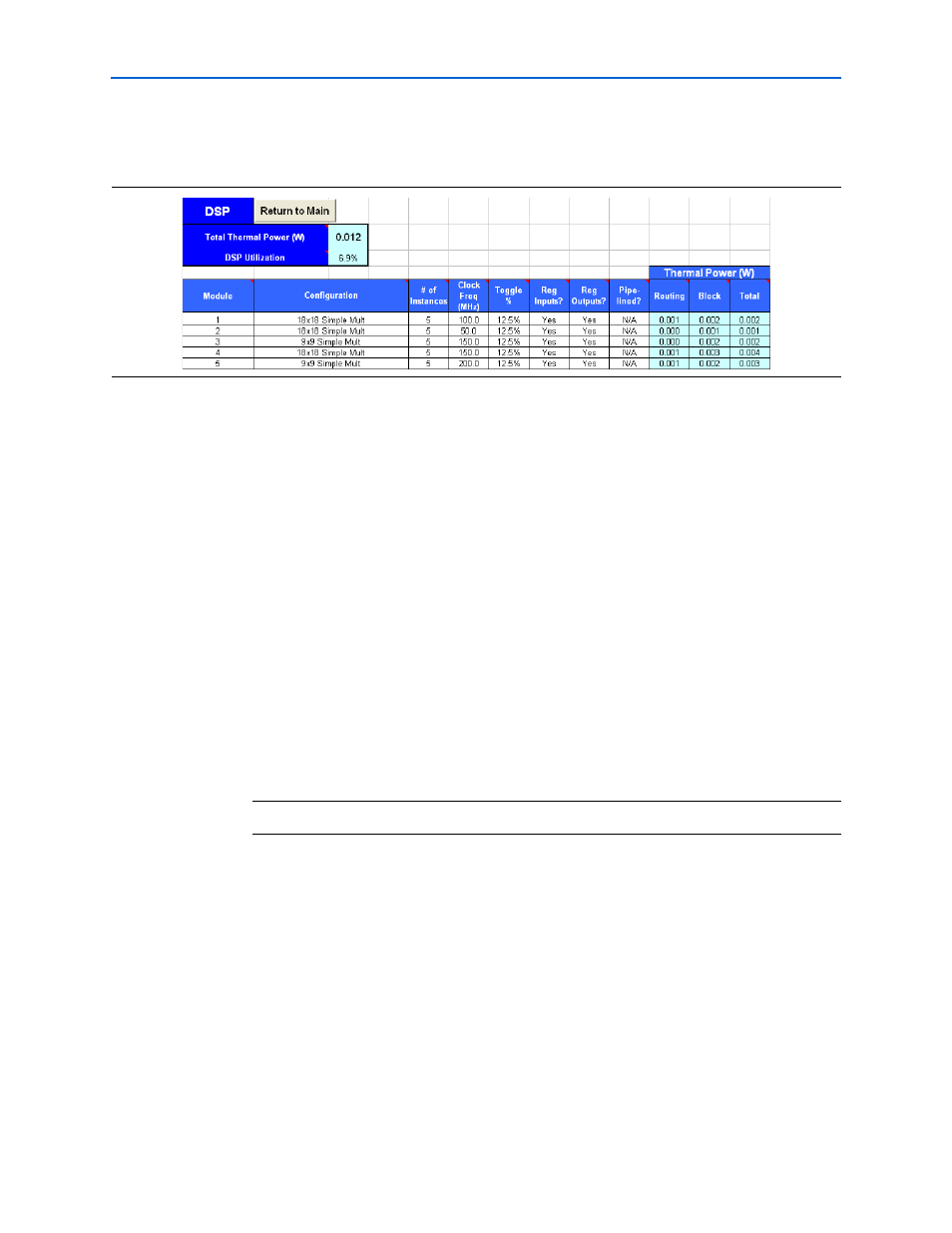
Figure 3–6
shows the DSP section of the PowerPlay Early Power Estimator and the
estimated power consumed by the DSP blocks.
General I/O Pins
Cyclone III device family feature programmable I/O pins that support a wide range
of industry I/O standards for increased design flexibility. The I/O section in the
PowerPlay Early Power Estimator allows you to estimate the I/O pin power
consumption based on the I/O standard of the pin.
1
The PowerPlay Early Power Estimator assumes that you are using external
termination resistors when you design with I/O standards that recommend
termination resistors (for example, SSTL and HSTL). If your design does not use
external termination resistors, Altera recommends choosing the LVTTL/LVCMOS
I/O standard with the same V
CCIO
and similar current strength as the terminated I/O
standard. For example, if you are using the SSTL-2 Class II I/O standard without
termination resistors (using a point-to-point connection), you should select 2.5 V as
your I/O standard in the PowerPlay Early Power Estimator.
The power reported for I/O signals includes thermal and external I/O power. The
total thermal power is the sum of the thermal power consumed by the device from
each power rail as specified in
.
Figure 3–6. DSP Section in the PowerPlay Early Power Estimator
Equation 3–1. Sum of The Thermal Power.
thermal power = thermal P
INT
+ thermal P
IO