Toggle rate, Toggle rate –24 – Altera PowerPlay Early Power Estimator User Manual
Page 36
3–24
Chapter 3: Using Cyclone III PowerPlay Early Power Estimator
Factors Affecting PowerPlay Early Power Estimator Accuracy
PowerPlay Early Power Estimator User Guide for Cyclone III FPGAs
© June 2009 Altera Corporation
Factors Affecting PowerPlay Early Power Estimator Accuracy
There are many factors that greatly affect the estimated values displayed in the
PowerPlay Early Power Estimator. You must determine if the input parameters
entered are accurate to ensure that the system is modeled correctly in the PowerPlay
Early Power Estimator. In particular, information entered concerning toggle rates,
airflow, temperature, and heat sinks are extremely important.
Toggle Rate
The toggle rates specified in the PowerPlay Early Power Estimator can have a very
large impact on the dynamic power consumption displayed. In order to obtain an
accurate estimate, you must input toggle rates that are realistic. Determining realistic
toggle rates is a non-trivial problem that requires the designer to know what kind of
input the FPGA is receiving and how often it toggles.
If the design is not yet complete, it is very difficult to get an accurate estimate. The
best way to approach the problem is to isolate the separate modules in the design by
functionality and estimate resource usage along with toggle rates of the resources. The
easiest way to accomplish this is to leverage previous designs to estimate toggle rates
for modules with similar functionality.
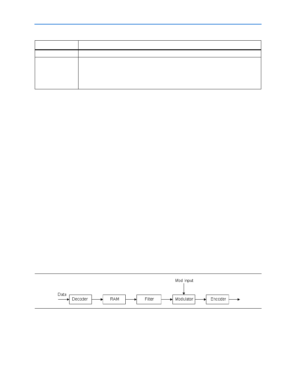
For example, assume that there is a simple design with an input data bus that has
been encoded for data transmission and has a roughly 50% toggle rate. The design
then goes through a decoder and is stored in RAM. The data is then filtered before
being modulated with another input data bus and the result is encoded for
transmission.
A simple block diagram is shown in
Figure 3–20
.
I
CCD
This shows the total current drawn from the V
CCD
supply (in A).
I
CCIO
This shows the total current drawn from the V
CCIO
power rail or rails. See the I/O sheet for details on
the current drawn from each I/O rail.
I
CCIO
includes any current drawn through the I/O into off-chip termination resistors. This can result
in I
CCIO
values that are higher than the reported I/O thermal power, since this off-chip current is
dissipated as heat elsewhere and does not factor into the calculation of device temperature.
Table 3–11. Power Supply Current Information (Part 2 of 2)
Parameter
Description
Figure 3–20. Decoder and Encoder Block Diagram