Ram blocks, Ram blocks –6, Clock frequency (in mhz) – Altera PowerPlay Early Power Estimator User Manual
Page 18: The percentage of time the ram clock is enabled, Figure 3–3. 4-bit counter example
3–6
Chapter 3: Using Cyclone III PowerPlay Early Power Estimator
PowerPlay Early Power Estimator Inputs
PowerPlay Early Power Estimator User Guide for Cyclone III FPGAs
© June 2009 Altera Corporation
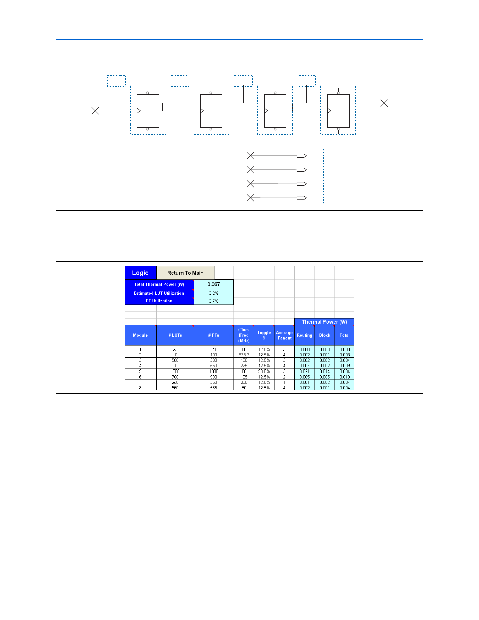
Figure 3–4
shows the Logic section in the PowerPlay Early Power Estimator and the
estimated power consumed by the logic.
RAM Blocks
Cyclone III device family feature M9K RAM blocks.
Each row in the RAM section represents a design module where the RAM blocks have
the same data width, RAM depth, RAM mode, port parameters, and output toggle
rate. If some or all the RAM blocks in your design have different configurations, enter
the information in different rows. For each design module, you must enter the
number of RAM blocks, the data width, the RAM mode, and the output toggle rate.
You must also enter the following parameters for each port:
■
Clock frequency (in MHz)
■
The percentage of time the RAM clock is enabled
■
The percentage of time the port is writing compared to reading
Figure 3–3. 4-Bit Counter Example
PRN
CLRN
T
Q
TFF
PRN
CLRN
T
Q
TFF
PRN
CLRN
T
Q
TFF
PRN
CLRN
T
Q
TFF
V
CC
V
CC
V
CC
V
CC
cout2
cout1
cout0
clock
cout3
OUTPUT
cout0
cout0
OUTPUT
cout3
cout3
OUTPUT
cout2
cout2
OUTPUT
cout1
cout1
Figure 3–4. Logic Section in the PowerPlay Early Power Estimator