Setup elements, Setup elements –17, Board settings dip switch –17 – Altera Arria II GX FPGA Development Board, 6G Edition User Manual
Page 25
Chapter 2: Board Components
2–17
Configuration, Status, and Setup Elements
© July 2010 Altera Corporation
Arria II GX FPGA Development Board, 6G Edition Reference Manual
lists the board-specific LEDs component references and manufacturing
information.
Setup Elements
The development board includes several different kinds of setup elements. This
section describes the following setup elements:
■
Board settings DIP switch
■
JTAG chain header switch
■
PCI Express control DIP switch
■
Reset configuration push-button switches
Board Settings DIP Switch
The board settings DIP switch (SW4) controls various features specific to the board
and the MAX
II CPLD EPM2210 System Controller logic design.
shows the
switch controls and descriptions.
D23
10
Green LED. Illuminates to indicate Ethernet linked at 10 Mbps connection speed.
Driven by the Marvell 88E1111 PHY.
D22
100
Green LED. Illuminates to indicate Ethernet linked at 100 Mbps connection speed.
Driven by the Marvell 88E1111 PHY.
D21
1000
Green LED. Illuminates to indicate Ethernet linked at 1000 Mbps connection speed.
Driven by the Marvell 88E1111 PHY.
D6
HSMC Port A
Present
Green LED. Illuminates when HSMC port A has a board or cable plugged-in such
that pin 160 becomes grounded. Driven by the add-in card.
D1
HSMC Port B
Present
Green LED. Illuminates when HSMC port B has a board or cable plugged-in such
that pin 160 becomes grounded. Driven by the add-in card.
D24
PCIe x1
Green LED. Configure this LED to display the PCI Express link width x1.
D25
PCIe x4
Green LED. Configure this LED to display the PCI Express link width x4.
D26
PCIe x8
Green LED. Configure this LED to display the PCI Express link width x8.
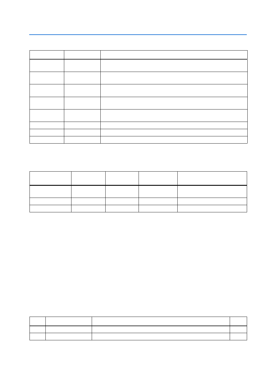
Table 2–10. Board-Specific LEDs (Part 2 of 2)
Board Reference
LED Name
Description
Table 2–11. Board-Specific LEDs Component References and Manufacturing Information
Board Reference
Description
Manufacturer
Manufacturer
Part Number
Manufacturer Website
D1, D6, D11-D16,
D19-D26
Green LEDs
Lite-On
LTST-C170KGKT
D16
Red LED
Lite-On
LTST-C170KRKT
D18
Blue LED
Lite-On
LTST-C170TBKT
Table 2–12. Board Settings DIP Switch Controls (Part 1 of 2)
Switch Schematic Signal Name
Description
Default
1
MAX_DIP0
Reserved
OFF
2
MAX_DIP1
Reserved
OFF