Encoder interfaces – Altera Multiaxis Motor Control Board User Manual
Page 11
Functional Description
Page 11
Multiaxis Motor Control Board
February 2014
Altera Corporation
Table 4
lists the ADCs.
Encoder Interfaces
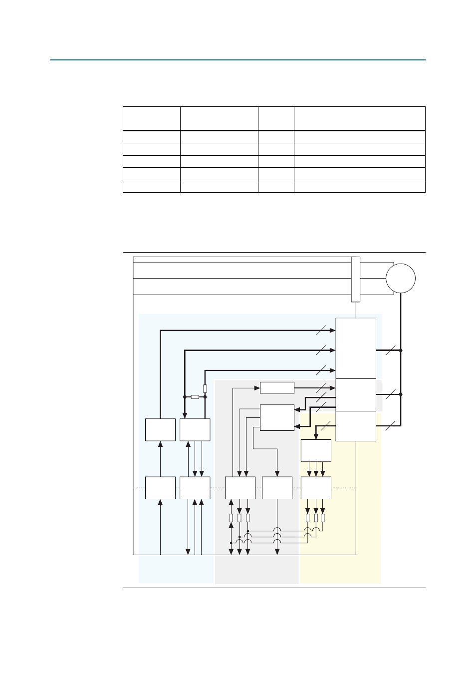
Figure 7
shows the encoder interface.
Table 4. ADCs
ADC
Measured Quantity
Scaling
Factor
HSMC Signals
DC-link monitor
DC-link voltage
0.048
HSMC_ADC_400V_PFC_V_DATA
DC-link monitor
DC-link current
1.95
HSMC_ADC_400V_PFC_I_DATA
IGBT return
IGBT return current
0.195
DRV_x_HSMC_MOTOR_RTN_DATA_OUT
Motor phase U
Motor phase U current
0.195
DRV_x_HSMC_U_DATA_OUT
Motor phase W
Motor phase W current
0.195
DRV_x_HSMC_W_DATA_OUT
Figure 7. Encoder Interface
5 V
3.3 V
3.3 V
3.3 V
3.3 V
3.3 V
3.3 V
3.3 V
5 V
5 V
3.3 V
3.3 V
x2
x2
6
6
6
SE to Diff
SD-ADC
10 MSPS
RS-485
Transceiver
RS-485
Transceiver
Isolator
RS-485
Transceiver
Isolator
Isolator
Isolator
Isolator
2
2
2
2
2
2
6
Resolver
SinCos
Quadrature/
Hall Effect
M
EnDAT
BiSS
Hiperface
EnDat, BiSS, and
HiperFace DSL
Encoder Interfaces
Resolver Sine and Cosine
Encoder Interface
Quadrature and Hall Effect
Encoder Interface