Hsmc isolator power supply, References – Altera Multiaxis Motor Control Board User Manual
Page 21
References
Page 21
Multiaxis Motor Control Board
February 2014
Altera Corporation
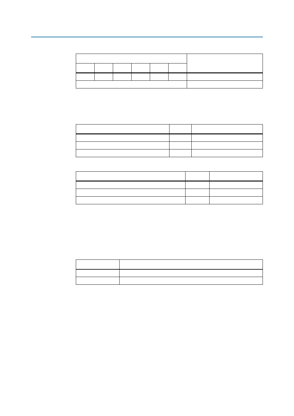
The function of the three DRV_x_HSMC_RSLVR_DRV_HALL_QUAD_y signals on the HSMC
changes according to the jumper settings for resolver (
Table 15
) and Hall effect and
quadrature (
Table 16
).
HSMC Isolator Power Supply
You may source the power supply for the host FPGA board side of the isolators
directly from the HSMC 3.3-V supply or derive it from the HSMC 12-V supply by a
switching regulator module (
Table 17
). This feature allows for situations where
insufficient power is available from one or the other of the HSMC supplies.
References
■
Altera Multiaxis Motor Control Board Schematics
■
Astec AIF – PFC 1600W AC-DC Converter Module Technical Reference Note
■
Fairchild FNB41560/B2 Smart Power Module Data Sheet
■
Fairchild AN-9070 Smart Power Module Motion-SPM Products Application Note
■
Analog Devices AD7401 Isolated Sigma-Delta Modulator Data Sheet
Out
Out
Out
In
In
In
Hall effect, quadrature.
All other combinations
Invalid.
Table 15. Resolver Interface Signals
Signal
Direction
Function
DRV_x_HSMC_RSLVR_DRV_HALL_QUAD_A
Input
Resolver drive.
DRV_x_HSMC_RSLVR_COS_HALL_QUAD_B
Output
Resolver cosine ADC bitstream.
DRV_x_HSMC_RSLVR_SIN_HALL_QUAD_C
Output
Resolver sine ADC bitstream.
Table 16. Hall Effect and Quadrature Signals
Signal
Direction
Function
DRV_x_HSMC_RSLVR_DRV_HALL_QUAD_A
Output
Channel A.
DRV_x_HSMC_RSLVR_COS_HALL_QUAD_B
Output
Channel B.
DRV_x_HSMC_RSLVR_SIN_HALL_QUAD_C
Output
Channel C.
Table 14. Encoder Interface Selection
Jumper Positions
Encoder Interface
A
B
C
D
E
F
Table 17. Isolator Isolated Power Supply
J58 Pins Linked
Isolator 3.3V_ISO Power Supply
1 to 2
3.3-V auxiliary from HSMC 12 V via LTM8022 module.
2 to 3
Direct from HSMC 3/3 V.